1. Introduction
This manual provides essential information for the safe and efficient operation of the SICK DT50-P1113 Industrial Distance Sensor. It covers installation, configuration, and maintenance procedures. Please read this manual thoroughly before operating the device.
2. Safety Information
The SICK DT50-P1113 is a Class 2 laser product. Observe all safety precautions to prevent injury.
- Laser Class: Class 2 Laser Product.
- Maximum Output: ≤ 180mW.
- Pulse Length: 5ns.
- Wavelength: 658nm.
- Compliance: Complies with EN/IEC 60825-1:2014 and 21 CFR 1040.10 and 1040.11 except for deviations pursuant to laser notice No. 50, dated June 24, 2007.
- Warning: Do not stare into the laser beam. Avoid direct eye exposure.
3. Product Overview
The SICK DT50-P1113 is an industrial distance sensor designed for precise measurement in various automation and manufacturing applications. It features a compact design, laser output, and robust construction.

Figure 3.1: This image displays the SICK DT50-P1113 Industrial Distance Sensor, highlighting its blue faceplate with detailed technical specifications and wiring diagram. Key information includes power supply (DC 10V...30V), output load (DC 30V, Q out ≤ 100mA, Q out 4mA...20mA), power consumption (max. 1.8W), operating temperature (-30°C...65°C), and laser safety warnings (Class 2, Max. Output ≤ 180mW, Pulse Length = 5ns, Wavelength = 658nm, EN/IEC 60825-1:2014 compliance).

Figure 3.2: The top of the sensor, revealing a small display screen and control buttons labeled 'Set', 'Esc', 'Up arrow', and 'Down arrow', used for configuration and operation.
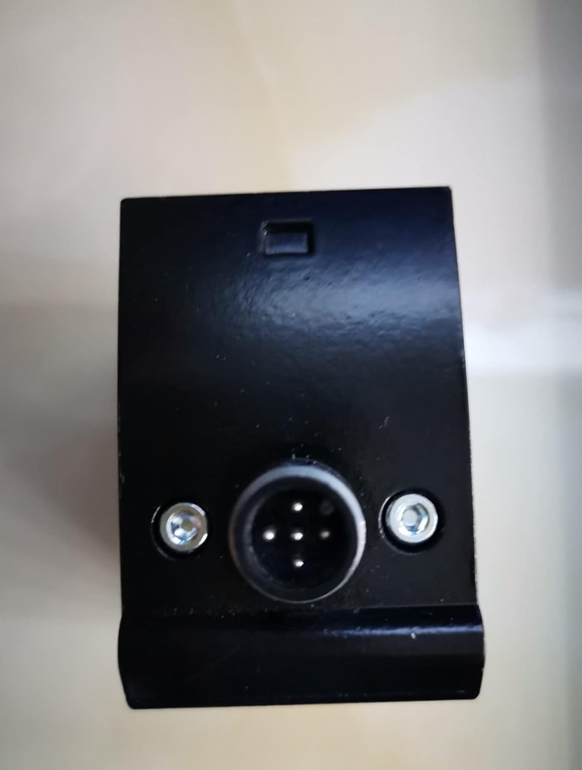
Figure 3.3: A view of the sensor's bottom, featuring the circular electrical connector and two mounting screws, indicating the flange mount design.
4. Technical Specifications
| Feature | Specification |
|---|---|
| Brand | Sick |
| Model Number | DT50-P1113 (Item model number: C-673248254, Manufacturer Part Number: DJSFHUI-13247) |
| Dimensions (L x W x H) | 1.18 x 0.39 x 9.84 inches |
| Mounting Type | Flange Mount |
| Output Type | Laser |
| Specific Uses | Industrial, Manufacturing, Automation |
| Power Supply | DC 10V ... 30V, Class 2 |
| Output Load | < DC 30V, Q out ≤ 100mA, Q out 4mA ... 20mA |
| Power Consumption | Max. 1.8W |
| Operating Temperature | -30°C ... 65°C |
| Enclosure Type | 1 |
| Date First Available | January 2, 2022 |
5. Setup and Installation
5.1. Mounting
The SICK DT50-P1113 sensor is designed for flange mounting. Secure the sensor using appropriate fasteners through the designated mounting holes. Ensure the mounting surface is stable and free from excessive vibration.
5.2. Electrical Connection
Connect the sensor to the power supply and control system according to the following wiring diagram. Ensure the power supply is within the specified range of DC 10V to 30V.
- Brown (Pin 1): L+ (Power Supply Positive)
- Blue (Pin 3): M (Power Supply Negative / Ground)
- Black (Pin 4): Q (Switching Output)
- White (Pin 2): QA (Analog Output / Second Switching Output)
- Gray (Pin 5): MF (Multi-Function Input)
Ensure all connections are secure and properly insulated to prevent short circuits or electrical hazards.
6. Operating Instructions
The sensor features a display and control buttons for configuration and monitoring. Refer to Figure 3.2 for button layout.
- Set Button: Used to enter menu, confirm selections, or save settings.
- Esc Button: Used to exit menus or cancel operations without saving.
- Up Arrow Button: Used to navigate menus or increase values.
- Down Arrow Button: Used to navigate menus or decrease values.
Specific parameter adjustments and operational modes are detailed in the full technical documentation provided by SICK. Always consult the comprehensive manual for advanced configuration.
7. Maintenance
The SICK DT50-P1113 sensor requires minimal maintenance to ensure optimal performance.
- Cleaning: Periodically clean the sensor's optical surfaces with a soft, lint-free cloth. Avoid abrasive cleaners or solvents that could damage the lens.
- Inspection: Regularly inspect the sensor for any signs of physical damage, loose connections, or environmental contamination.
- Environmental Conditions: Ensure the sensor operates within its specified temperature range (-30°C to 65°C) and enclosure type (Type 1) to prevent damage.
8. Troubleshooting
If the sensor is not functioning as expected, consider the following basic troubleshooting steps:
- No Power: Check the power supply connections (L+ and M) and ensure the voltage is within DC 10V-30V.
- No Output Signal: Verify the wiring for the Q and QA outputs. Check sensor configuration via the control buttons and display.
- Inaccurate Readings: Ensure the optical path is clear and free from obstructions. Clean the sensor lens if necessary. Verify mounting stability.
- Environmental Factors: Confirm that the operating temperature and humidity are within the sensor's specifications.
For persistent issues, consult the detailed SICK technical documentation or contact SICK customer support.
9. Warranty and Support
For information regarding product warranty, technical support, or service, please refer to the official SICK documentation provided with your purchase or visit the SICK website. Keep your purchase receipt and product serial number readily available when contacting support.