1. Safety Information
Please read and understand all safety information and operating instructions before using this digital multimeter. Failure to follow these safety guidelines may result in electric shock, fire, or damage to the meter or the equipment under test.
- Always ensure the multimeter is in the correct function and range for the measurement being performed.
- Do not exceed the maximum input values specified for each range.
- Exercise extreme caution when working with voltages above 30V AC RMS, 42V peak, or 60V DC. These voltages pose a shock hazard.
- Before measuring current, ensure the circuit is de-energized and the meter is connected in series.
- Always disconnect the test leads from the circuit before changing functions or ranges.
- Inspect test leads for damaged insulation or exposed metal before each use. Replace if damaged.
- Do not operate the meter if it appears damaged or if the battery cover is not properly closed.
- Replace fuses with the specified type and rating only. Refer to the back panel for fuse specifications.
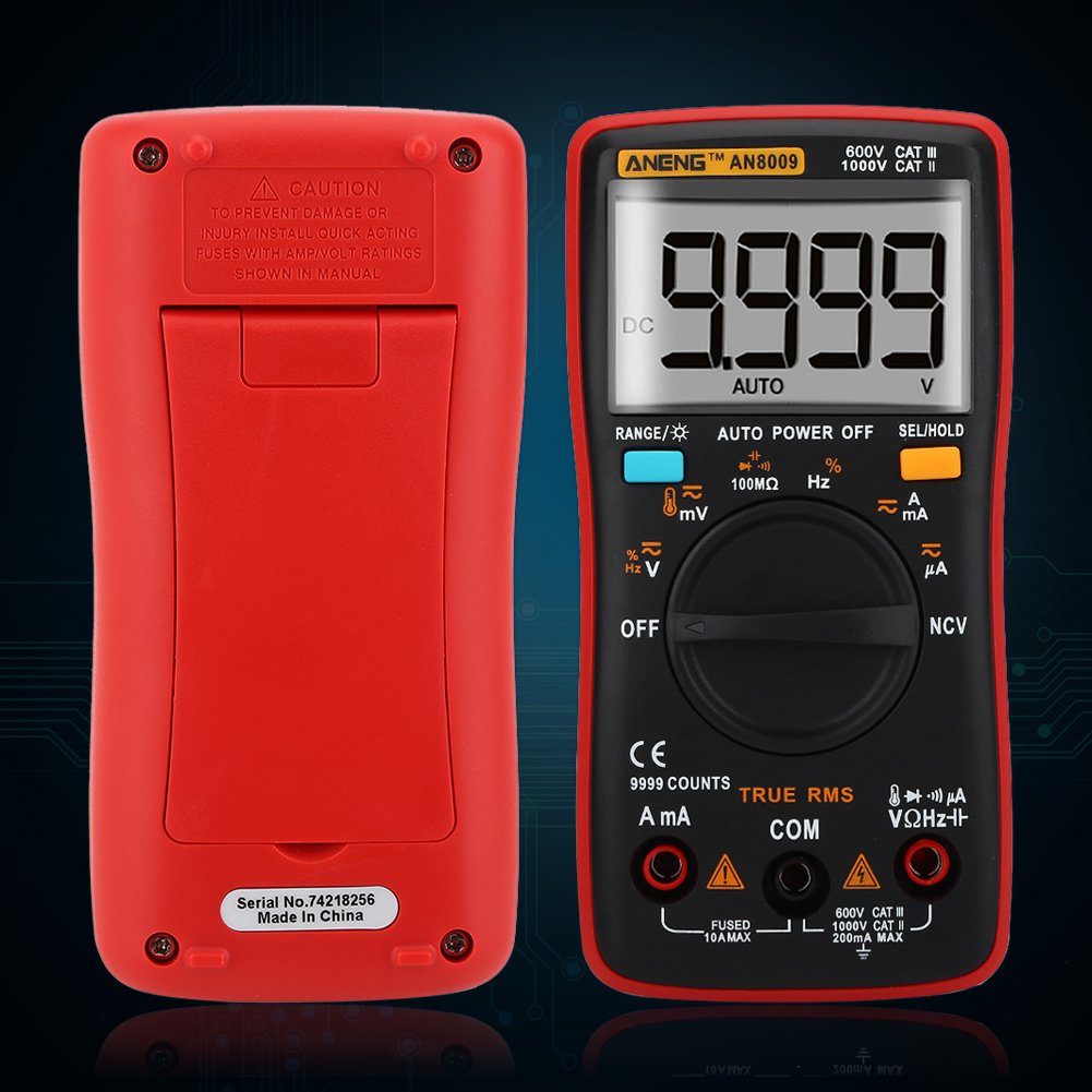
Figure 1.1: Back view of the ANENG AN8009 Multimeter, showing the battery compartment and a caution label regarding fuse installation and voltage ratings.
2. Product Overview
The ANENG AN8009 is a portable, auto-ranging digital multimeter designed for measuring AC/DC voltage, AC/DC current, resistance, capacitance, frequency, temperature, diode, and continuity. It features a large backlit LCD display for clear readings and a compact ergonomic design.
2.1. Meter Components

Figure 2.1: Front view of the ANENG AN8009 Digital Multimeter with key components labeled.
- LED Display: Shows measurement readings, units, and function indicators.
- Data Hold Key: Press to freeze the current reading on the display. Press again to release.
- Backlight Button: Activates or deactivates the display backlight for improved visibility in low-light conditions.
- Range Switch: Used to select measurement functions (e.g., Voltage, Current, Resistance, etc.).
- Remaining Measurement Input Port (VΩHz): Input for voltage, resistance, frequency, capacitance, and diode measurements.
- 10A Current Input: Input for high current measurements (up to 10A).
- COM Input: Common (negative) input terminal for all measurements.
- µA/mA Current Input: Input for low current measurements (microamperes and milliamperes).
2.2. Display Indicators
The LCD display provides various indicators to assist with measurements:
- AUTO: Indicates auto-ranging mode is active.
- DC/AC: Indicates Direct Current or Alternating Current measurement.
- HOLD: Indicates data hold function is active.
- Battery Symbol: Indicates low battery power. Replace batteries promptly.
- Units: Displays appropriate units such as V, mV, A, mA, µA, Ω, kΩ, MΩ, F, nF, µF, Hz, kHz, MHz, °C, °F.
3. Setup
3.1. Battery Installation
The ANENG AN8009 multimeter requires two 1.5V AAA batteries (not included) for operation.
- Ensure the multimeter is turned OFF.
- Locate the battery compartment on the back of the meter.
- Use a screwdriver to remove the screws securing the battery cover.
- Carefully remove the battery cover.
- Insert two 1.5V AAA batteries, observing the correct polarity (+ and -) as indicated inside the compartment.
- Replace the battery cover and secure it with the screws.
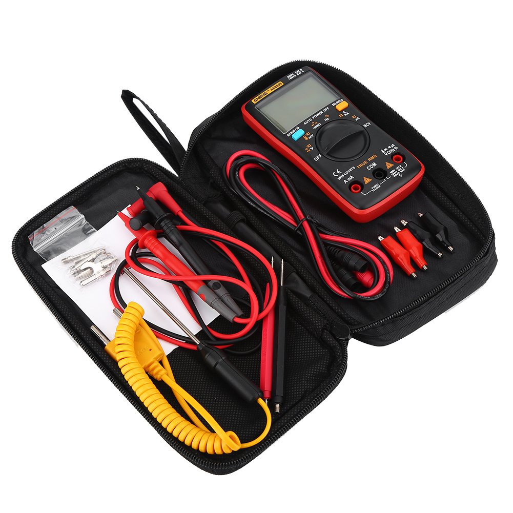
Figure 3.1: Front and back view of the ANENG AN8009 Multimeter, showing the location of the battery compartment on the back.
3.2. Test Lead Connection
Proper connection of test leads is crucial for accurate and safe measurements.
- Connect the black test lead to the COM (Common) input jack.
- For voltage, resistance, frequency, capacitance, and diode measurements, connect the red test lead to the VΩHz input jack.
- For current measurements (µA/mA), connect the red test lead to the µA/mA input jack.
- For high current measurements (up to 10A), connect the red test lead to the 10A input jack.

Figure 3.2: Close-up view of the test lead connectors, showing the standard banana plug design for secure connection to the multimeter input jacks.

Figure 3.3: The ANENG AN8009 Multimeter being held with test leads properly connected, ready for various electrical measurements.
4. Operating Instructions
This section details how to perform various measurements using the ANENG AN8009 Digital Multimeter.
4.1. General Operation
- Power On/Off: Rotate the Range Switch from OFF to any desired function to turn on the meter. Rotate back to OFF to power off.
- Auto/Manual Ranging: The meter defaults to auto-ranging. For specific ranges, consult the manual for manual range selection if available for a particular function.
- Data Hold: Press the 'HOLD' button to freeze the current reading on the display. Press again to release.
- Backlight: Press the backlight button to illuminate the display. Press again to turn off.
4.2. AC/DC Voltage Measurement
- Connect the red test lead to the VΩHz jack and the black test lead to the COM jack.
- Rotate the Range Switch to the 'V~' (AC Voltage) or 'V-' (DC Voltage) position.
- Connect the test probes in parallel to the circuit or component under test.
- Read the voltage value on the display.
4.3. AC/DC Current Measurement
Caution: Never connect the meter in parallel to a voltage source when measuring current. This can damage the meter and the circuit.
- Connect the black test lead to the COM jack.
- For currents up to 600mA, connect the red test lead to the µA/mA jack. For currents up to 10A, connect the red test lead to the 10A jack.
- Rotate the Range Switch to the 'A~' (AC Current) or 'A-' (DC Current) position.
- Open the circuit where current is to be measured and connect the meter in series with the load.
- Read the current value on the display.
4.4. Resistance Measurement
- Connect the red test lead to the VΩHz jack and the black test lead to the COM jack.
- Rotate the Range Switch to the 'Ω' (Resistance) position.
- Ensure the circuit or component under test is de-energized.
- Connect the test probes across the component to measure its resistance.
- Read the resistance value on the display.
4.5. Capacitance Measurement
- Connect the red test lead to the VΩHz jack and the black test lead to the COM jack.
- Rotate the Range Switch to the 'F' (Capacitance) position.
- Ensure the capacitor is fully discharged before measurement to prevent damage to the meter.
- Connect the test probes across the capacitor.
- Read the capacitance value on the display.
4.6. Frequency Measurement
- Connect the red test lead to the VΩHz jack and the black test lead to the COM jack.
- Rotate the Range Switch to the 'Hz' (Frequency) position.
- Connect the test probes in parallel to the signal source.
- Read the frequency value on the display.
4.7. Temperature Measurement
- Connect the temperature sensor (thermocouple) to the VΩHz and COM jacks, observing polarity if applicable.
- Rotate the Range Switch to the '°C/°F' (Temperature) position.
- Place the tip of the temperature sensor on or near the object whose temperature is to be measured.
- Read the temperature value on the display.

Figure 4.1: The ANENG AN8009 Multimeter connected with a temperature probe, demonstrating its capability for temperature measurement.
4.8. Diode Test
- Connect the red test lead to the VΩHz jack and the black test lead to the COM jack.
- Rotate the Range Switch to the 'Diode' symbol position.
- Connect the red probe to the anode and the black probe to the cathode of the diode.
- A forward voltage drop will be displayed for a good diode. Reverse the probes; the display should show 'OL' (Open Loop).
4.9. Continuity Test
- Connect the red test lead to the VΩHz jack and the black test lead to the COM jack.
- Rotate the Range Switch to the 'Continuity' symbol position.
- Connect the test probes across the circuit or component.
- If the resistance is below a certain threshold (typically 50Ω), the meter will emit an audible beep, indicating continuity.
4.10. Non-Contact Voltage (NCV) Detection
- Rotate the Range Switch to the 'NCV' position.
- Move the top edge of the meter near a live AC voltage source.
- The meter will emit an audible beep and the NCV indicator will light up, indicating the presence of AC voltage.
4.11. Square Wave Output
- Rotate the Range Switch to the 'Square Wave' symbol position.
- The meter will output a square wave signal at the VΩHz terminal.
- The frequency of the square wave can be selected from the available options (e.g., 50Hz to 1000Hz).
5. Maintenance
5.1. Cleaning
To clean the meter, wipe the case with a damp cloth and a mild detergent. Do not use abrasives or solvents. Ensure the meter is completely dry before use.
5.2. Battery Replacement
When the battery symbol appears on the display, replace the batteries immediately to ensure accurate readings. Refer to Section 3.1 for battery installation instructions.
5.3. Fuse Replacement
If the current measurement function fails, the fuse may need replacement. Refer to the caution label on the back of the meter for the correct fuse type and rating. Always replace with a fuse of identical specifications to prevent damage or fire hazard.
6. Troubleshooting
- No display or faint display: Check battery installation and charge. Replace batteries if necessary.
- 'OL' (Overload) displayed: The measured value exceeds the selected range. Switch to a higher range or ensure the input is within the meter's capabilities.
- Incorrect readings: Ensure test leads are properly connected, the correct function is selected, and the circuit is properly set up for measurement. Check for damaged test leads.
- Current measurement not working: Check the fuse. Replace if blown (refer to Section 5.3).
7. Specifications
| Parameter | Value |
|---|---|
| Brand Name | ANENG |
| Model Number | AN8009 |
| Operating Temperature | 0 - 40 ℃ |
| Operating Humidity | ≤75%RH |
| Storage Condition | -20~60℃ |
| Storage Humidity | ≤80%RH |
| Operating Mode | Auto/Manual Ranging |
| Measuring Temperature Range | -20~1000 C / -4F-1832F |
| Measuring Capacitance Range | 9.99nF/99.99nF/999.9nF/9.99uF/99.99uF/999.9uF/9.999MF |
| Measuring Voltage Range | 999.9mV/9.999V/99.99V/999.9V |
| Measuring Current Range | 60mA/600mA/10A |
| Measuring Resistance Range | 99.99/999.9/9.999k/99.99k/999.9K/999.9M |
| Frequency | 99.99Hz/999.9Hz/9.999KHz/99.99KHz/999.9KHz/9.999MHz |
| Square Wave Output | 50Hz/100Hz/200Hz/300Hz/400Hz/500Hz/600Hz/700Hz/800Hz/900Hz/1000Hz |
| DC/AC Voltage (mV) | 9.999mV/99.99mV |
| DC/AC Voltage (V) | 999.9mV/9.999V/99.99V/750ACV(999.9DCV) |
| DC/AC Current (mA&A) | 999.9mA/9.999A |
| DC/AC Current (uA) | 99.99µA/999.9µA |
| Display Type | Digital Display |
| Diode Test | Yes |
| Continuity | Yes |
| Duty Cycle | 1%-99% |
| Sample Rate | 3 times per second |
| Power Supply | 2 x 1.5V AAA batteries (Not Included) |
| Size | Approx. 130 x 65 x 30mm / 5.12 x 2.56 x 1.18inch |
| Weight | 345g |
8. Package Contents
The package for your ANENG AN8009 Digital Multimeter includes the following items:
- 1 x Multimeter (ANENG AN8009)
- 1 x Test lead + Temperature sensor
- 16 x Test Probe (various types)
- 1 x Storage Bag
- 1 x User Manual (this document)

Figure 8.1: An assortment of test probes and accessories included with the multimeter, offering versatility for various measurement tasks.
9. Warranty and Support
For warranty information and technical support, please refer to the documentation provided at the time of purchase or contact your retailer. Keep your purchase receipt as proof of purchase for any warranty claims.


