1. Introduction
This manual provides essential information for the proper installation, operation, and maintenance of your Powermaster 482378 Alternator. Please read this manual thoroughly before attempting any installation or operation to ensure safety and optimal performance of the unit.
2. Safety Information
- Always disconnect the vehicle's battery before working on the electrical system to prevent electrical shock or damage to components.
- Wear appropriate personal protective equipment, including safety glasses and gloves, during installation.
- Ensure all connections are clean, tight, and free from corrosion to prevent poor performance or electrical fires.
- Consult a qualified automotive technician if you are unsure about any installation steps or electrical procedures.
- Keep hands and clothing clear of moving parts when the engine is running.
3. Product Overview
The Powermaster 482378 is a high-performance alternator designed for GM applications, featuring an XS Volt™ 220A output with a 6-groove pulley. This unit is engineered for a great output-to-weight ratio and is race-inspired for demanding applications.
Understanding the alternator's power curve is crucial for optimal performance, especially when considering custom pulley sets. The output of an alternator is dependent on speed and follows a unique curve. Small changes in speed, particularly at idle, can significantly impact output capacity.
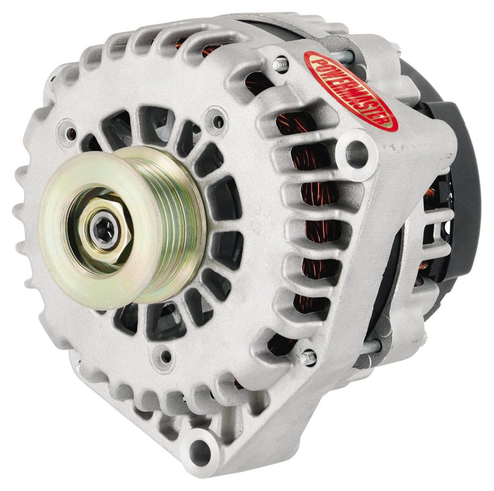
Figure 1: Powermaster 482378 Alternator. This image shows the general appearance of the Powermaster 482378 alternator, highlighting its compact design and pulley system.
4. Setup and Installation
Proper installation is critical for the longevity and performance of your Powermaster alternator. It is highly recommended that installation be performed by a professional automotive technician.
4.1 Pulley Ratios
Pulley ratios are very important, especially with high amperage alternators. The pulley supplied with the alternator is matched to its winding and power curve. It is essential that any aftermarket or 'dress-up' pulley sets do not deviate from this ratio.
- A street-driven vehicle should typically have a pulley ratio of at least 3:1.
- For vehicles with automatic transmissions, low idle speeds, and significant cruising time, a higher pulley ratio, such as 3.5:1, may be beneficial.
- Alternators can withstand speeds up to 20,000 RPMs for short durations, so overdriving the unit is generally not an issue.
- Important: The output of high-amp alternators can decrease substantially below 2400 rotor RPMs. Powermaster does not recommend using 'power pulleys' with high-amp alternators if they alter the recommended ratio.
4.2 General Installation Steps (Consult vehicle-specific service manual for detailed instructions)
- Disconnect the negative battery terminal.
- Remove the serpentine belt or V-belt from the old alternator.
- Disconnect all electrical connections from the old alternator (battery cable, exciter wire, etc.).
- Unbolt and remove the old alternator.
- Install the new Powermaster 482378 alternator, ensuring proper alignment and secure mounting.
- Reconnect all electrical connections, ensuring they are clean and tight.
- Reinstall the serpentine belt, ensuring proper tension.
- Reconnect the negative battery terminal.
- Start the engine and check for proper charging voltage.
5. Operating Instructions
Once installed, the Powermaster 482378 alternator operates automatically to maintain the vehicle's electrical system voltage and recharge the battery. No specific user interaction is required during normal operation.
However, it is important to understand the factors affecting its performance:
- Engine Speed: The alternator's output is directly related to engine speed. At lower engine RPMs (e.g., idle), the alternator's output capacity will be lower than at higher RPMs.
- Electrical Load: The more electrical accessories (lights, stereo, air conditioning, etc.) are active, the higher the demand on the alternator. The 220A capacity of this unit is designed to handle significant electrical loads.
- Pulley Ratio: As discussed in the installation section, the correct pulley ratio ensures the alternator operates within its optimal speed range, especially at idle, to provide sufficient output.
Powermaster utilizes state-of-the-art computer alternator dynos to measure the performance of each alternator, carefully considering output curves, engine idle speeds, and alternator pulley ratios to ensure good drivability at idle and slow cruising speeds.
6. Maintenance
Regular maintenance helps ensure the longevity and reliable operation of your alternator.
- Belt Inspection: Periodically check the serpentine belt for cracks, fraying, or excessive wear. Ensure it has the correct tension. A loose belt can cause slippage, reducing alternator output and generating heat.
- Electrical Connections: Inspect all electrical connections to the alternator for corrosion, looseness, or damage. Clean any corrosion and ensure connections are tight.
- Battery Condition: A healthy battery is crucial for alternator performance. Ensure your vehicle's battery is in good condition and properly charged.
- Cleanliness: Keep the alternator free from excessive dirt, oil, and debris, which can impede cooling and affect performance.
7. Troubleshooting
If you experience issues with your vehicle's charging system, consider the following common troubleshooting steps:
- Battery Warning Light On: This typically indicates a problem with the charging system. Check the alternator belt for tension and condition. Inspect all electrical connections for looseness or corrosion. Test the battery and alternator output.
- Dim Lights or Electrical Malfunctions: This could indicate low voltage output from the alternator. Check belt tension, connections, and have the alternator tested.
- Unusual Noises: Squealing or grinding noises from the alternator area can indicate a worn belt, loose pulley, or internal bearing failure. Address these issues promptly.
- Overcharging: If the battery is constantly overcharged (e.g., boiling electrolyte), the voltage regulator within the alternator may be faulty.
For complex issues, it is recommended to seek assistance from a certified automotive technician.
8. Specifications
| Specification | Detail |
|---|---|
| Model Name | 482378 |
| Brand | POWERMASTER |
| Output Amperage | 220A |
| Grooves | 6 grv |
| Compatibility | GM applications |
| Color | Silver |
| Material | Plastic (housing/components) |
| Item Dimensions (LxWxH) | 9.25 x 7.5 x 7.25 inches |
| Package Weight | 1 Pounds |
| Included Components | Powermaster - Alt GM Natural XS Volt™ 220A 6 grv |
9. Warranty Information
This Powermaster 482378 Alternator is covered by a Manufacturer Warranty. For specific details regarding warranty terms, conditions, and duration, please refer to the documentation provided with your purchase or contact Powermaster directly.
10. Support
For technical assistance, troubleshooting, or warranty claims, please contact Powermaster customer support. Have your product model number (482378) and purchase information ready when contacting support.
You can typically find contact information on the manufacturer's official website or in the packaging materials.


