
1. Introduction
This manual provides essential information for the safe and effective use of the AITRIP 1.5A Multi-Function Mini Boost Module. This module is designed to convert a lower input voltage, typically from a 3.7V lithium battery, into a higher, stable output voltage of 5V, 8V, 9V, or 12V. Please read this manual thoroughly before operation.
2. Safety Information
- Always ensure correct polarity when connecting input and output power. Incorrect connections can damage the module and connected devices.
- Do not exceed the maximum input voltage or output current specifications.
- Handle the module with care to avoid physical damage to components or solder joints.
- Ensure proper insulation to prevent short circuits, especially when integrating into other circuits.
- Keep the module away from moisture, dust, and extreme temperatures.
3. Product Overview
The AITRIP Mini Boost Module is a compact step-up converter designed for various electronic projects requiring a higher voltage from a low-voltage source. It features adjustable output voltage settings and an LED indicator for operational status.
Key Features:
- Adjustable Output Voltage: 5V, 8V, 9V, 12V (default 12V).
- Wide Input Voltage Range: 2.5V to VOUT-0.5V.
- Maximum Output Current: Up to 1A (depending on input/output voltage).
- Compact Size: 22mm x 11mm x 3.6mm.
- Integrated LED indicator.
Module Components:
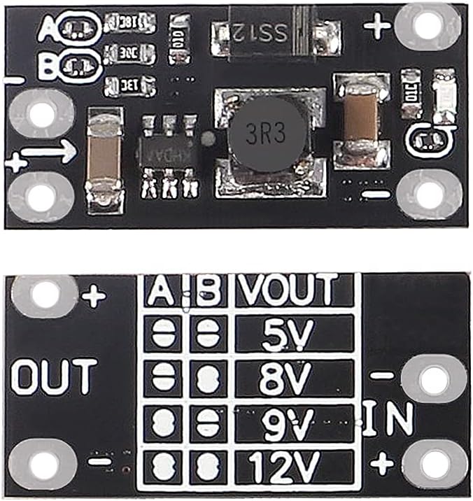
The module features clearly labeled input (IN) and output (OUT) pads, along with 'A' and 'B' pads for voltage selection. The LED indicator illuminates when the module is active.

4. Specifications
| Parameter | Value |
|---|---|
| Brand | AITRIP |
| Model Number | 048df8a6-387a-4e93-a925-640386d530f4 |
| Input Voltage Range | 2.5V to VOUT-0.5V |
| Output Voltage Options | 5V, 8V, 9V, 12V (Default: 12V) |
| Maximum Output Current | 1.5A (ensure input/output current does not exceed 1.5A) |
| Typical Output Performance (3.7V input) | 5V@1A, 8V@0.7A, 9V@0.6A, 12V@0.5A |
| Product Dimensions | 22mm × 11mm × 3.6mm |
| LED Indicator Current Consumption | Approximately 6mA (when on) |
| UPC/GTIN | 701715486621 |
5. Setup
5.1. Connecting Input Power
Connect your low-voltage DC power source (e.g., a 3.7V lithium battery) to the IN+ and IN- pads on the module. Ensure correct polarity: IN+ for positive, IN- for negative.
5.2. Connecting Output Load
Connect your device or circuit requiring the boosted voltage to the OUT+ and OUT- pads. Ensure correct polarity: OUT+ for positive, OUT- for negative.
5.3. Setting Output Voltage
The output voltage of the module is adjustable by soldering the 'A' and 'B' pads located on the module. The default output voltage is 12V. To change the output voltage, use a soldering iron to connect (solder a bridge) or disconnect (leave open) the 'A' and 'B' pads according to the table below:
| A Pad | B Pad | Output Voltage (VOUT) |
|---|---|---|
| Disconnected (0) | Disconnected (0) | 5V |
| Disconnected (0) | Connected (1) | 8V |
| Connected (1) | Disconnected (0) | 9V |
| Connected (1) | Connected (1) | 12V (Default) |
Note: '0' indicates the pad is disconnected (no solder bridge), and '1' indicates the pad is connected (solder bridge applied).
6. Operating Instructions
Once the input power and output load are connected, and the desired output voltage is set via the A/B pads, the module will automatically begin stepping up the input voltage to the configured output voltage. The onboard LED indicator will illuminate to show that the module is powered and operating.
- Monitor the input voltage to ensure it remains within the specified range (2.5V to VOUT-0.5V).
- Ensure the total current drawn by your load does not exceed the module's maximum output current of 1.5A. Exceeding this limit can lead to unstable output or damage to the module.
- If the LED indicator is off, check the input power supply and connections.
7. Maintenance
- Keep the module clean and free from dust and debris. Use a soft, dry brush if cleaning is necessary.
- Regularly inspect solder joints and connections for any signs of wear or damage.
- Store the module in a dry, cool environment when not in use.
- Avoid applying excessive mechanical stress to the module.
8. Troubleshooting
8.1. No Output Voltage / LED Off
- Check Input Power: Verify that the input voltage is present and within the specified range (2.5V to VOUT-0.5V).
- Check Connections: Ensure all input and output connections are secure and correctly polarized.
- Verify Voltage Setting: Confirm that the A/B pads are correctly configured for the desired output voltage.
8.2. Output Voltage is Lower Than Expected
- Input Voltage Too Low: The input voltage might be too close to the output voltage, or below the minimum required for stable regulation.
- Exceeding Current Limit: The connected load may be drawing more current than the module can supply, causing voltage sag. Reduce the load or ensure the total current draw is within the 1.5A limit.
- Capacitor Recommendation: For applications with high initial current draw or motors, adding a good quality 100uF electrolytic capacitor on both the input and output may improve stability and prevent undervoltage shutdowns.
8.3. Module Shuts Down Intermittently
- This can indicate an overcurrent or undervoltage protection triggering. Disconnect and reconnect the input power to reset the module.
- Review the load current and input voltage stability.
9. Warranty and Support
Specific warranty details for this product are not provided in this manual. For warranty claims, technical support, or further assistance, please contact the seller or manufacturer, AITRIP, directly through the platform where the product was purchased. You can typically find contact information on the product's listing page or your order history.
For general inquiries, please refer to the product page: AITRIP Mini Boost Module on Amazon