1. Introduction
The Sonel CMM 30 is an advanced industrial multimeter engineered for versatility, modern functionality, and exceptional durability. This device integrates 11 fundamental measurement functions along with additional features, providing a broad spectrum of applications for professionals. Its robust design includes drop protection and an IP67 rated casing, ensuring reliable performance even in challenging environments.
Key features include a smartphone application for remote reading and data saving via wireless communication, an automatically adjusting backlight for optimal screen visibility, and a built-in flashlight for illumination in dark conditions. This manual provides essential information for the safe and effective use of your CMM 30 multimeter.
2. Safety Information
Always adhere to the following safety precautions to prevent electric shock, injury, or damage to the meter or equipment under test.
- Read and understand all instructions and safety information in this manual before operating the meter.
- Do not use the meter if it appears damaged or if the insulation on the test leads is compromised.
- Always disconnect power to the circuit and discharge all high-voltage capacitors before making resistance, continuity, diode, or capacitance measurements.
- Use caution when working with voltages above 30V AC RMS, 42V peak, or 60V DC. These voltages pose a shock hazard.
- Do not exceed the maximum input limits for any function.
- Ensure the function switch is in the correct position for the desired measurement before connecting the test leads to the circuit.
- Replace batteries as soon as the low battery indicator appears to ensure accurate readings.
- Do not operate the meter in explosive gas, vapor, or dust environments.
3. Package Contents
Verify that all items listed below are present and undamaged upon opening the package:
- Sonel CMM 30 Industrial Multimeter
- Test Leads (Red and Black)
- Temperature Probe (K-type thermocouple)
- 4 x AAA Batteries (pre-installed or separate)
- User Manual (this document)
If any items are missing or damaged, please contact your supplier immediately.
4. Product Overview
Familiarize yourself with the components of your Sonel CMM 30 multimeter:
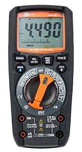
Figure 4.1: Front view of the Sonel CMM 30 Industrial Multimeter. This image displays the device's main components, including the digital display, the central rotary function switch, and the various input terminals for test leads.
4.1. Display
The large LCD shows measurement readings, units, function indicators, and battery status. It features an automatic backlight that adjusts to ambient light conditions for optimal visibility.
4.2. Rotary Function Switch
This central switch is used to select the desired measurement function (e.g., Voltage, Current, Resistance, Capacitance, Temperature, Frequency).
4.3. Function Buttons
Various buttons provide additional controls and features:
- RANGE: Toggles between manual and automatic ranging.
- MODE: Selects sub-functions within a main rotary switch position (e.g., AC/DC voltage, Diode/Continuity).
- HOLD: Freezes the current display reading.
- MAX/MIN/AVG: Records maximum, minimum, and average readings.
- REL: Relative mode, subtracts a stored value from subsequent measurements.
- Bluetooth/Light: Activates Bluetooth connectivity for the smartphone app and controls the built-in flashlight.
4.4. Input Jacks
These are the connection points for the test leads:
- COM: Common terminal for the black test lead.
- VΩHzCAP°C: Input for voltage, resistance, frequency, capacitance, and temperature measurements (red test lead).
- mAµA: Input for milliampere and microampere current measurements (red test lead).
- 10A: Input for up to 10 Ampere current measurements (red test lead).
5. Setup
5.1. Battery Installation
The Sonel CMM 30 requires 4 AAA batteries. These may be pre-installed or included separately.
- Ensure the multimeter is turned OFF.
- Locate the battery compartment on the rear of the meter.
- Use a screwdriver to loosen the screw(s) securing the battery cover.
- Remove the battery cover.
- Insert the 4 AAA batteries, observing the correct polarity (+ and -) as indicated inside the compartment.
- Replace the battery cover and tighten the screw(s) securely.
Note: Always use fresh batteries of the same type. Remove batteries if the meter is not used for an extended period to prevent leakage.
6. Operating Instructions
6.1. Powering On/Off
Turn the rotary function switch from the OFF position to any desired measurement function to power on the meter. To power off, turn the switch back to the OFF position.
6.2. Basic Measurement Procedures
Before any measurement, ensure the test leads are correctly inserted into the appropriate input jacks for the selected function.
6.2.1. Voltage Measurement (AC/DC)
- Insert the black test lead into the COM jack and the red test lead into the VΩHzCAP°C jack.
- Turn the rotary switch to the V~ (AC Voltage) or V- (DC Voltage) position. If both are combined, use the MODE button to select AC or DC.
- Connect the test leads in parallel across the circuit or component to be measured.
- Read the voltage value on the display.
6.2.2. Current Measurement (AC/DC)
Caution: Never connect the meter in parallel for current measurement. Always connect in series with the circuit.
- Insert the black test lead into the COM jack. For currents up to 10A, insert the red test lead into the 10A jack. For smaller currents (mA/µA), insert the red test lead into the mAµA jack.
- Turn the rotary switch to the A~ (AC Current) or A- (DC Current) position, or the mA/µA position as appropriate. Use the MODE button to select AC or DC if needed.
- Open the circuit where current is to be measured and connect the meter in series.
- Read the current value on the display.
6.2.3. Resistance Measurement
- Insert the black test lead into the COM jack and the red test lead into the VΩHzCAP°C jack.
- Turn the rotary switch to the Ω (Resistance) position.
- Ensure the circuit or component is de-energized before connecting the test leads across it.
- Read the resistance value on the display.
6.2.4. Capacitance Measurement
- Insert the black test lead into the COM jack and the red test lead into the VΩHzCAP°C jack.
- Turn the rotary switch to the CAP (Capacitance) position.
- Ensure the capacitor is fully discharged before connecting the test leads across it.
- Read the capacitance value on the display.
6.2.5. Temperature Measurement
- Insert the temperature probe into the VΩHzCAP°C and COM jacks, observing polarity if applicable.
- Turn the rotary switch to the °C/°F (Temperature) position.
- Place the tip of the temperature probe on or near the object whose temperature is to be measured.
- Read the temperature value on the display.
6.3. Advanced Features
6.3.1. True RMS Measurement
The CMM 30 features True RMS for AC voltage and current measurements, providing accurate readings for non-sinusoidal waveforms.
6.3.2. Wireless Communication and Smartphone App
The CMM 30 can connect wirelessly to a smartphone application, allowing for remote reading and saving of measurements. This is particularly useful in hard-to-reach or hazardous locations.
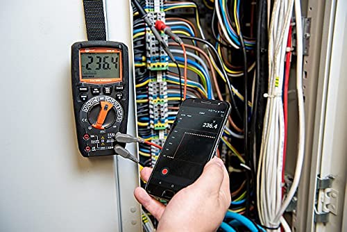
Figure 6.1: The Sonel CMM 30 Multimeter connected to an electrical panel, demonstrating its wireless communication feature. A smartphone displays the measurement reading remotely, highlighting the convenience for inaccessible areas.
To use this feature:
- Download the official Sonel CMM app from your smartphone's app store.
- Enable Bluetooth on your smartphone.
- Press the Bluetooth button on the multimeter to activate its wireless communication.
- Follow the app's instructions to pair with your CMM 30 and begin remote monitoring.
6.3.3. Built-in Flashlight
The integrated flashlight assists in illuminating measurement areas, especially in low-light conditions. Activate it by pressing the dedicated light button.
6.4. Durability and IP67 Rating
The CMM 30 is designed with an IP67 rating, signifying its protection against dust ingress and immersion in water up to 1 meter for 30 minutes. This makes it suitable for demanding industrial environments.
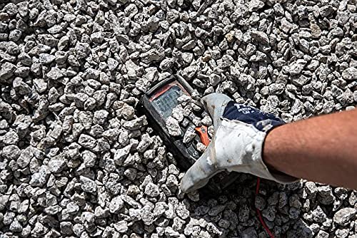
Figure 6.2: The Sonel CMM 30 Multimeter partially submerged in gravel, illustrating its robust construction and resistance to dust and debris, a testament to its IP67 rating.

Figure 6.3: The Sonel CMM 30 Multimeter creating a splash as it impacts a muddy puddle, demonstrating its exceptional water resistance and ability to withstand harsh, wet conditions.
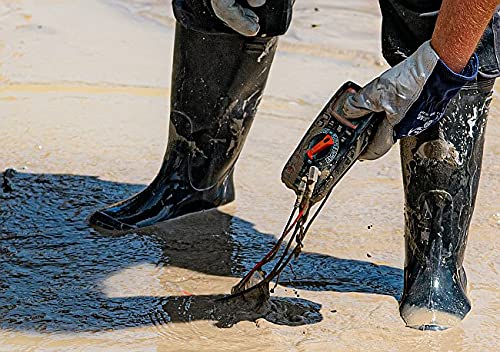
Figure 6.4: A person, wearing protective boots and gloves, retrieves the Sonel CMM 30 Multimeter from a muddy environment. This image emphasizes the device's resilience and ease of handling even after exposure to challenging conditions.
7. Maintenance
7.1. Cleaning
Wipe the meter's casing with a damp cloth and a mild detergent. Do not use abrasives or solvents. Ensure the meter is completely dry before use.
7.2. Battery Replacement
Refer to Section 5.1 for battery replacement instructions. Replace batteries promptly when the low battery indicator appears on the display.
7.3. Storage
When not in use for extended periods, store the multimeter in a dry, cool place, away from direct sunlight and extreme temperatures. Remove the batteries to prevent leakage.
8. Troubleshooting
| Problem | Possible Cause | Solution |
|---|---|---|
| Meter does not power on. | Dead or incorrectly installed batteries. | Check battery polarity or replace batteries. |
| No reading or "OL" (Overload) displayed. | Incorrect function selected; open circuit; measurement exceeds range. | Select correct function; check circuit continuity; switch to a higher range or auto-range. |
| Inaccurate readings. | Low battery; dirty test leads/jacks; external interference. | Replace batteries; clean leads/jacks; move away from strong electromagnetic fields. |
| Bluetooth connection issues. | Bluetooth not enabled on meter/phone; app issues; distance. | Ensure Bluetooth is on; restart app/phone; reduce distance between devices. |
9. Specifications
| Feature | Specification |
|---|---|
| Brand | Sonel |
| Model Number | SON001 |
| Colour | Black |
| Item Weight | 418 g |
| Package Dimensions | 30 x 15 x 10 cm |
| Batteries | 4 AAA batteries required (included) |
| Measurement Functions | AC/DC Voltage, AC/DC Current, Resistance, Capacity, Temperature, Duty Cycle, Frequency |
| Ranging | Manual and Automatic |
| True RMS | Yes (for AC voltage and current) |
| Ingress Protection (IP) Rating | IP67 |
| Connectivity | Wireless (Smartphone App) |
| Additional Features | HOLD function, Built-in flashlight, Backlight auto-adjustment |
10. Warranty and Support
10.1. Warranty Information
Sonel products are manufactured to high standards and are warranted against defects in materials and workmanship for a period specified by your regional distributor from the date of purchase. This warranty does not cover damage caused by misuse, unauthorized modification, accident, or neglect. Please retain your proof of purchase for warranty claims.
10.2. Technical Support
For technical assistance, troubleshooting beyond this manual, or warranty inquiries, please contact your local Sonel distributor or the authorized service center. Contact information can typically be found on the Sonel official website or through your point of purchase.
When contacting support, please have your product model number (SON001) and purchase date readily available.


