EPEVER IP1500-12 Plus
EPEVER IPower-Plus Series IP1500-12 Plus Pure Sine Wave Inverter
User Instruction Manual
1. Introduction
This manual provides detailed instructions for the installation, operation, and maintenance of your EPEVER IPower-Plus Series IP1500-12 Plus Pure Sine Wave Inverter. This 1500W 12VDC to 230VAC inverter is designed for off-grid systems, household lighting, vehicle-mounted systems, and other applications requiring reliable AC power from a DC source.
The IPower-Plus series features a 180-degree rotatable LCD display, compatibility with lithium batteries, a USB port (for 12V/24V models), and transient suppression on the input side to protect battery cells and Battery Management Systems (BMS) from transient current damage. It also boasts low idle current consumption.
2. Important Safety Instructions
Please read all instructions and warnings carefully before installation and operation. Failure to follow these instructions may result in electric shock, fire, or severe injury.
- Ensure the inverter is installed in a well-ventilated area, away from flammable materials and moisture.
- Do not expose the inverter to rain, snow, spray, or any liquids.
- Do not operate the inverter if it has been damaged in any way.
- All electrical installations must comply with local and national electrical codes.
- Only qualified personnel should perform electrical connections.
- Disconnect all power sources before performing any maintenance or troubleshooting.
- Ensure the DC input voltage matches the inverter's rated voltage (12VDC for this model).
- Do not connect the inverter to an AC utility grid.
- Keep children away from the inverter.
3. Product Overview
The EPEVER IPower-Plus inverter is designed for robust performance and ease of use. Below are key components and their functions.

Figure 3.1: Front View with LCD Display. This image shows the front of the EPEVER IPower-Plus inverter, highlighting the central LCD display which provides real-time operational data such as output voltage and fault indicators. The display is rotatable for optimal viewing.
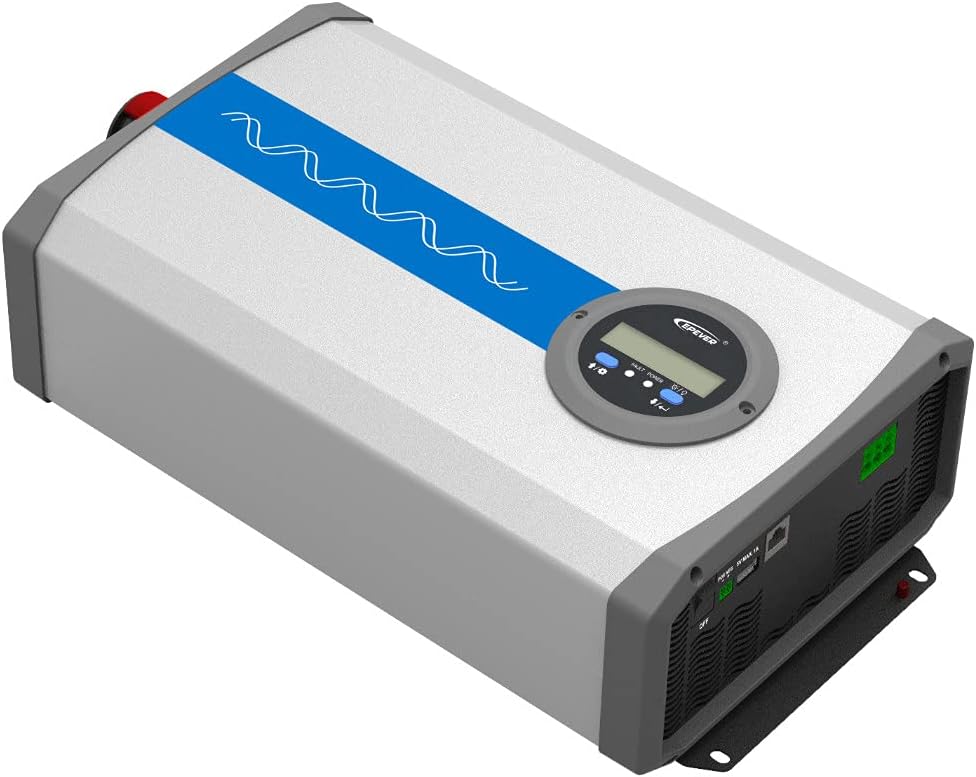
Figure 3.2: Angled Top View. This perspective shows the overall compact design of the inverter, with the blue stripe indicating the pure sine wave output capability. The robust casing ensures durability.

Figure 3.3: Angled Bottom View. This view highlights the mounting brackets at the base of the inverter, designed for secure installation on various surfaces.

Figure 3.4: Rear Panel Connections. The rear panel features the AC output terminals (N, L), an RS485 communication interface for remote monitoring, a 5VDC/1A USB output port, and the main ON/OFF power switch.

Figure 3.5: Front Panel DC Input and Fans. This image displays the DC input terminals (positive and negative) for connecting to the battery bank, along with the integrated cooling fans that ensure optimal operating temperature.

Figure 3.6: Side View with Product Label. The side of the inverter shows the product label, which includes model information, serial number, and certification marks.
4. Setup and Installation
4.1 Site Selection
- Install the inverter indoors, away from direct sunlight, high temperatures, and high humidity.
- Ensure adequate airflow around the inverter for proper cooling. Maintain at least 15 cm (6 inches) of clearance around all sides.
- Mount the inverter vertically on a non-flammable surface.
4.2 Wiring Connections
- DC Input Connection:
- Ensure the inverter's ON/OFF switch is in the "OFF" position.
- Connect the positive (+) terminal of the battery bank to the positive (+) DC input terminal of the inverter.
- Connect the negative (-) terminal of the battery bank to the negative (-) DC input terminal of the inverter.
- Use appropriate gauge cables for the DC connections to minimize voltage drop and ensure safety.
- Tighten all connections securely to prevent loose contacts and overheating.
- AC Output Connection:
- Connect your AC loads to the AC output terminals (N, L) on the rear panel.
- Ensure the total power consumption of your AC loads does not exceed the inverter's continuous output power (1500W).
- For safety, it is recommended to connect the inverter's chassis to an earth ground.
- Optional Connections (RS485 & USB):
- The RS485 interface allows for remote monitoring and control via PC software or mobile app. Connect an RS485 communication cable if desired.
- The USB port provides a 5VDC/1A output for charging small electronic devices.
Warning: Incorrect wiring can cause severe damage to the inverter and connected devices. Always double-check polarity before powering on.
5. Operating Instructions
5.1 Powering On/Off
- After all connections are secure, switch the ON/OFF button on the rear panel to the "ON" position.
- The LCD display will illuminate, showing the output voltage and other operational parameters.
- To power off, switch the ON/OFF button to the "OFF" position.
5.2 LCD Display and Indicators
The LCD display provides real-time information about the inverter's status. It can be rotated 180 degrees for convenient viewing.
- Output Voltage: Displays the current AC output voltage (e.g., 220.0V).
- Fault/Power Indicator: Indicates operational status or error codes.
- Battery Voltage: Shows the DC input voltage from the battery.
- Load Power: Displays the current power consumption of connected AC loads.
5.3 USB and RS485 Usage
- USB Port: Connect compatible USB devices for charging. The output is 5VDC, Max. 1A.
- RS485 Interface: Use this port with an appropriate communication module (sold separately) to connect to a PC or mobile device for advanced monitoring, data logging, and parameter settings via EPEVER's software or app.
6. Maintenance
Regular maintenance ensures the longevity and optimal performance of your inverter.
- Cleaning: Periodically clean the inverter's exterior with a dry cloth. Ensure ventilation openings are free from dust and debris. Do not use liquid cleaners.
- Connections: Annually check all electrical connections (DC input and AC output) for tightness. Loose connections can cause overheating and damage.
- Environment: Ensure the installation environment remains within the specified temperature and humidity ranges.
- Battery Health: Monitor your battery bank's health and charge level regularly, as it directly impacts inverter performance.
7. Troubleshooting
This section provides solutions to common issues you might encounter.
| Problem | Possible Cause | Solution |
|---|---|---|
| No AC Output / Inverter not turning on |
|
|
| Overload Alarm |
|
|
| Over-temperature Alarm |
|
|
| Abnormal Output Voltage |
|
|
If the problem persists after trying the above solutions, please contact EPEVER customer support.
8. Technical Specifications
| Feature | Specification |
|---|---|
| Brand | EPEVER |
| Model Name | IPower-Plus Series IP1500-12 Plus |
| System Battery Voltage | 12V DC |
| Continuous Power | 1500W |
| Pulse Power (5s) | 3000W |
| Output Voltage | 220VAC (±3%); 230VAC (-7%~+3%) |
| Output Frequency | 50/60Hz ±0.2% |
| Maximum Efficiency | >93% (30% load) |
| Idle Current | <1.2A |
| USB Output | 5VDC/Max. 1A |
| RS485 Interface Output | 5VDC/200mA |
| Protection Class | IP20 |
| Dimensions (L×W×H) | 387 × 231.5 × 123 mm |
| Net Weight | 6 kg |
| Safety Protections | Reverse polarity, Over-voltage, Low voltage, Overload, Short-circuit, Over-temperature |
9. Warranty and Support
9.1 Warranty Information
The EPEVER IPower-Plus Series IP1500-12 Plus inverter comes with a 2-year manufacturer's warranty from the date of purchase. This warranty covers defects in materials and workmanship under normal use.
The warranty does not cover damage caused by:
- Improper installation or wiring.
- Unauthorized modifications or repairs.
- Accidents, abuse, or neglect.
- Natural disasters or acts of God.
- Operating outside specified environmental conditions.
Please retain your proof of purchase for warranty claims.
9.2 Customer Support
For technical assistance, troubleshooting beyond this manual, or warranty claims, please contact your authorized EPEVER dealer or visit the official EPEVER website for support contact information.
Manufacturer: SolarV (Brand: EPEVER)
For more information, you can visit the EPEVER Brand Store.
Ask a question about this manual
Ask about setup, troubleshooting, compatibility, parts, safety, or missing instructions. Manuals+ will review the question and use this page’s manual context to help answer it.