
1. Introduction
The DKARDU USB Logic Analyzer Device (Model JK-US-155) is an 8-channel digital logic analyzer designed for debugging various digital communication protocols. It is compatible with popular logic analyzer software such as Saleae Logic Analyzer and Sigrok PulseView. This device is suitable for analyzing signals in 5V, 3.3V, 2.5V, and 2.0V systems, and may also function with 1.8V systems, though it is not specifically recommended for optimal performance at that voltage.
The logic analyzer provides a sampling rate of up to 24MHz, with selectable rates including 16MHz, 12MHz, 8MHz, 4MHz, 2MHz, 1MHz, 500KHz, 250KHz, 200KHz, 100KHz, 50KHz, and 25KHz. It supports automatic analysis of common protocols such as UART, SPI, and IIC, facilitating efficient debugging of embedded systems, microcontrollers (SCM), FPGAs, and Arduino projects.

Figure 1: DKARDU USB Logic Analyzer Device, top view showing channel labels and USB port.
2. Setup
2.1 Package Contents
Before proceeding with the setup, ensure all components are present in the package:
- 1 x Logic Analyzer Unit
- 1 x Mini USB Cable
- 1 x 22-PIN Female-to-Female DuPont Cable
- 12 x Test Hook Clips
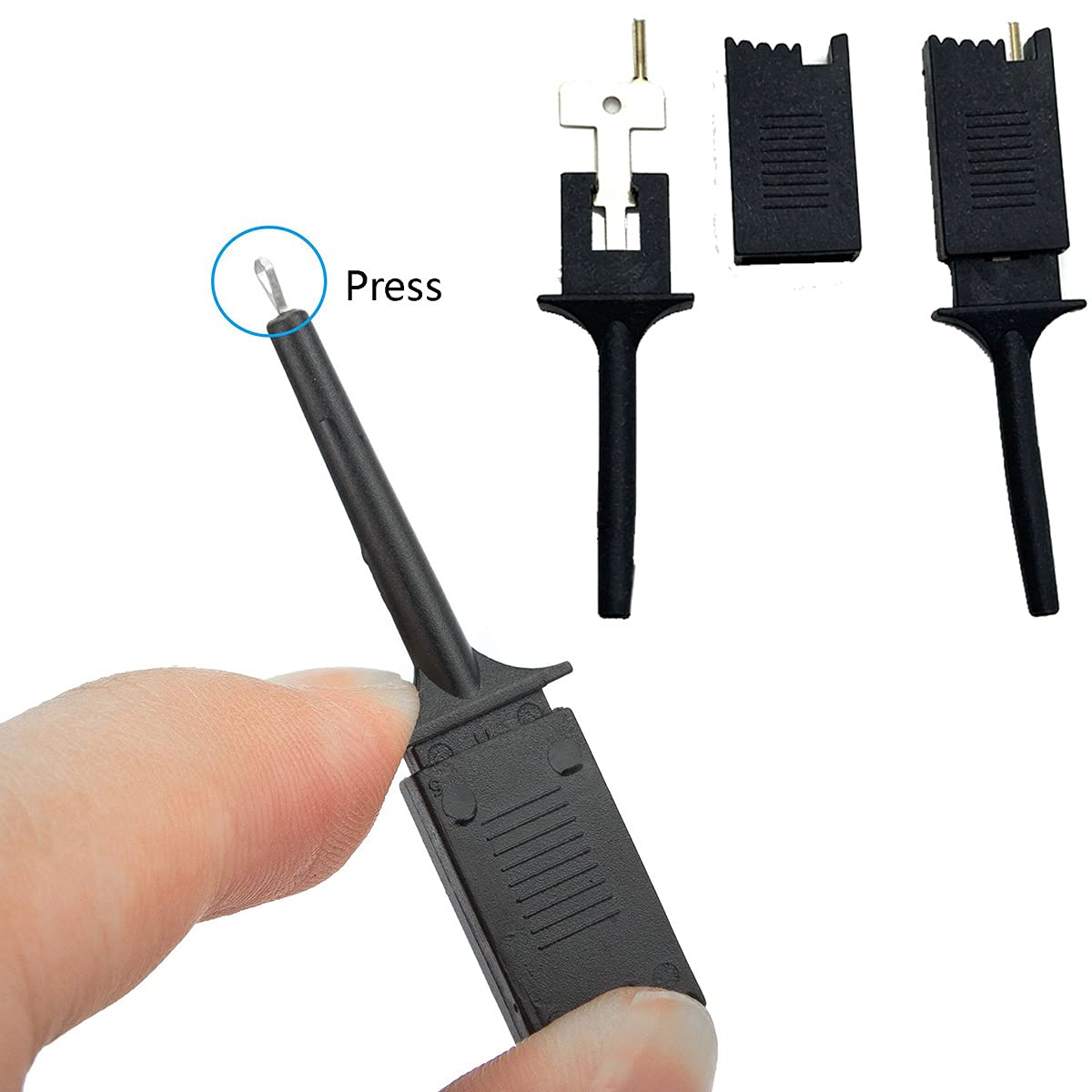
Figure 2: Included test hook clips. Press the top to open the clip for connection.
2.2 Software Installation
This logic analyzer requires third-party software for operation. It is compatible with Saleae Logic Analyzer software (e.g., Logic 2.4.x) and Sigrok PulseView. No proprietary software is included with the device.
- Download Software: Obtain the latest version of Saleae Logic Analyzer software or Sigrok PulseView from their respective official websites.
- Install Software: Follow the on-screen instructions to install the chosen software on your computer.
- Connect Device: Connect the logic analyzer to your computer using the provided Mini USB cable.
- Driver Installation:
- For Saleae Software: The Saleae Logic 2 software typically includes driver installation. Upon connecting the device, the software should recognize it and prompt for driver installation if necessary.
- For Sigrok PulseView: You may need to use a tool like Zadig (available online) to install the correct drivers.
- Run the Zadig utility.
- Select the logic analyzer device from the dropdown menu.
- Choose the appropriate driver (often WinUSB or libusb-win32) and click "Install Driver" or "Replace Driver".
- Verify Recognition: Launch the logic analyzer software. The device should be detected and ready for use.
Note: Some users have reported that the device may not achieve the full 24MHz sampling rate reliably with certain software or setups, often stabilizing around 16MHz. This can sometimes be mitigated by using a high-quality, shielded USB cable, though results may vary.
3. Operation
3.1 Connecting to a Circuit
The logic analyzer features 8 digital channels (CH1-CH8), a Power (PWR) pin, a Clock (CLK) pin, and a Ground (GND CH1) pin. Use the provided DuPont cables and test hook clips to connect the logic analyzer to your target circuit.
- Connect the GND CH1 pin of the logic analyzer to the ground of your target circuit. This is crucial for accurate measurements.
- Connect the CH1 through CH8 pins to the digital signals you wish to analyze.
- The PWR pin is typically an output from the logic analyzer, providing power to the target circuit if needed, but it's often not used for signal analysis.
- The CLK pin is for external clocking, if your application requires it. For most uses, the internal clock of the logic analyzer software is sufficient.

Figure 3: Example setup showing the logic analyzer connected to a breadboard circuit via test clips and DuPont cables.
3.2 Software Configuration and Analysis
Once connected and recognized by the software, configure the sampling parameters:
- Sampling Rate: Select the desired sampling rate within the software. Available rates include 24MHz, 16MHz, 12MHz, 8MHz, 4MHz, 2MHz, 1MHz, 500KHz, 250KHz, 200KHz, 100KHz, 50KHz, and 25KHz. A higher sampling rate captures more detail but uses more memory.
- Channel Assignment: Assign the connected channels (CH1-CH8) to the corresponding inputs in the software.
- Voltage Threshold: The device operates with a voltage threshold of 1.5V. Signals below 1.5V are interpreted as low, and signals above 1.5V are interpreted as high.
- Protocol Analyzers: Utilize the built-in protocol analyzers within the software (e.g., for UART, SPI, IIC) to automatically decode and display communication data. This significantly simplifies debugging.
Begin capturing data by initiating the capture function in your chosen software. Analyze the waveforms and decoded data to debug your digital circuits.
4. Maintenance
The DKARDU USB Logic Analyzer is a low-maintenance device. Follow these guidelines to ensure its longevity and proper function:
- Storage: Store the device in a dry, dust-free environment when not in use.
- Cleaning: Use a soft, dry cloth to clean the exterior of the device. Avoid using liquid cleaners or solvents.
- Cable Care: Handle the USB and DuPont cables carefully to prevent damage. Avoid sharp bends or excessive pulling.
- Environmental Conditions: Operate the device within typical indoor temperature and humidity ranges. Avoid extreme temperatures or high humidity.
5. Troubleshooting
This section addresses common issues you might encounter with the logic analyzer.
- Device Not Recognized:
- Ensure the Mini USB cable is securely connected to both the logic analyzer and your computer.
- Try a different USB port on your computer.
- Verify that the correct drivers are installed using Zadig for Sigrok PulseView, or ensure Saleae software has installed its drivers.
- Restart your computer and try again.
- Inaccurate Readings or No Signal:
- Confirm that the logic analyzer's GND CH1 pin is properly connected to the ground of your target circuit.
- Check all connections from the test clips to the DuPont cables and to the logic analyzer channels. Ensure they are firm.
- Verify that the target circuit is powered on and functioning correctly.
- Ensure the input voltage of your target circuit is within the logic analyzer's supported range (-0.5V to 5.25V).
- Adjust the sampling rate in the software. A rate too high for the signal frequency or too low for the device's capability can cause issues.
- Cannot Achieve 24MHz Sampling Rate:
- While rated for 24MHz, some setups may only reliably achieve up to 16MHz. This can be due to USB cable quality, computer USB controller, or software variations.
- Consider using a high-quality, shielded USB cable.
- If 16MHz is sufficient for your application, adjust your expectations or slow down the clock of your target circuit for debugging.
- Included Test Hook Clips Issues:
- Some users report the included clips may be of lower quality. If you experience unreliable connections, consider acquiring higher-quality test clips.
6. Specifications

Figure 4: Dimensions of the DKARDU USB Logic Analyzer Device.

Figure 5: Overview of key technical specifications.
| Feature | Value |
|---|---|
| Model Number | JK-US-155 |
| Channels | 8 Digital Channels |
| Maximum Sampling Rate | 24 MHz (selectable rates: 24MHz, 16MHz, 12MHz, 8MHz, 4MHz, 2MHz, 1MHz, 500KHz, 250KHz, 200KHz, 100KHz, 50KHz, 25KHz) |
| Input Voltage Range | -0.5V to 5.25V |
| Input Low Voltage | -0.5V to 0.8V |
| Input High Voltage | 2.0V to 5.25V |
| Voltage Threshold | 1.5V |
| Input Impedance | 1Mohm || 10pF (typical, approximate) |
| Crystal Accuracy | +/-20ppm, 24MHz |
| Pulse-width Measurement Error/Accuracy | +/- 42ns (at 24MHz) |
| Compatible Systems | 5V, 3.3V, 2.5V, 2.0V (may work with 1.8V, not recommended) |
| Power Source | USB Powered |
| Dimensions | 12.8 x 8.3 x 3 cm (Parcel); Device dimensions: 48mm x 28mm x 15mm (approx.) |
| Weight | 0.1 kg (Device) |
| Compatible Devices | Arduino, FPGA, SCM |
| Certifications Met | UL 61010-1, IEC 61010-2-030 |
7. Warranty Information
Specific warranty details for the DKARDU USB Logic Analyzer Device are not provided in the product information. For warranty inquiries, please refer to the retailer's return policy or contact the manufacturer directly.
Standard return policies typically allow for returns or replacements within a specified period (e.g., 30 days from purchase) for defective products.
8. Customer Support
For technical assistance, troubleshooting beyond this manual, or inquiries regarding your DKARDU USB Logic Analyzer Device, please contact the seller or manufacturer.
Manufacturer: DKARDU
Refer to your purchase documentation or the retailer's website for specific contact methods.