1. Introduction
This manual provides essential information for the safe and efficient installation, operation, and maintenance of the Sick TIM351-2134001 2D LiDAR Sensor. Please read this manual thoroughly before using the device and keep it for future reference.
The Sick TIM351-2134001 is a high-performance 2D LiDAR sensor designed for various industrial applications, offering precise distance measurement and object detection within its specified range and field of view.
2. Safety Information
Warning: Failure to follow these safety instructions may result in personal injury or damage to the equipment.
- Ensure all electrical connections are made by qualified personnel and comply with local electrical codes.
- Disconnect power before performing any installation, maintenance, or repair work.
- Do not operate the sensor in environments exceeding its specified operating conditions (e.g., temperature, humidity, IP rating).
- Avoid direct exposure of the eyes to the laser beam. Although this device uses a low-power laser, direct exposure can be harmful.
- Use only original Sick accessories and spare parts.
3. Product Overview
The Sick TIM351-2134001 is a robust 2D LiDAR sensor featuring a 0-8 meter scan range at 10% reflectivity and a 10-meter working range. It provides a wide 270-degree field of view, making it suitable for comprehensive area monitoring. The sensor is rated IP67 for protection against dust and water ingress, ensuring reliable operation in challenging industrial environments. It includes 4 digital inputs and 3 digital outputs for flexible integration.
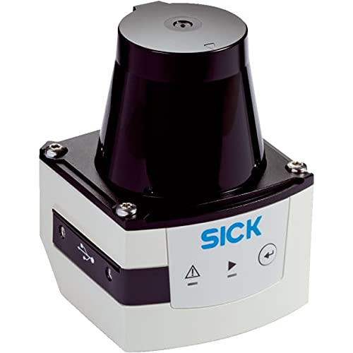
Figure 1: Front view of the Sick TIM351-2134001 2D LiDAR Sensor. This image shows the compact design and the main sensing window of the device.
4. Setup
4.1 Unpacking and Inspection
Carefully unpack the sensor and inspect it for any signs of damage. Report any damage to the shipping carrier and supplier immediately. Ensure all components listed in the packing slip are present.
4.2 Mounting
Mount the sensor securely using appropriate hardware. Ensure the mounting surface is stable and free from vibrations. Position the sensor to provide an unobstructed view of the area to be monitored, considering its 270-degree field of view. The IP67 rating allows for outdoor or harsh environment mounting, but ensure proper drainage if mounted in a position where water could accumulate.
4.3 Electrical Connection
The TIM351-2134001 is a corded electric device. Connect the sensor to a stable power supply within the specified voltage range. Refer to the wiring diagram (typically found in a separate technical data sheet or on the device label) for correct pin assignments for power, data communication, and the 4 digital inputs and 3 digital outputs. Ensure proper grounding.
- Power Supply: Connect to a regulated DC power source.
- I/O Connections: Utilize the 4 inputs and 3 outputs for integration with control systems or other devices.
- Data Interface: Connect the appropriate data cable for communication and configuration.
5. Operating Instructions
5.1 Powering On
Once all electrical connections are secure, apply power to the sensor. The sensor will typically perform a self-test upon startup. Observe any indicator lights for status feedback.
5.2 Configuration
The TIM351-2134001 requires configuration via its data interface (e.g., Ethernet, serial) using manufacturer-provided software. This software allows you to define scan parameters, detection zones, output behaviors for the 4/3 I/O, and other operational settings. Refer to the software manual for detailed configuration steps.
- Define the monitoring area within the 270-degree field of view.
- Set detection thresholds and response times.
- Configure the digital inputs for external control and outputs for alarm or status signaling.
5.3 Data Output
The sensor outputs 2D scan data, which can be processed by a host system for various applications such as navigation, collision avoidance, or presence detection. The digital outputs can be used to trigger external devices based on configured detection events.
6. Maintenance
6.1 Cleaning
Regularly clean the sensor's optical window to ensure optimal performance. Use a soft, lint-free cloth and a mild cleaning solution (e.g., isopropyl alcohol) if necessary. Do not use abrasive materials or harsh chemicals that could scratch the lens. The IP67 rating protects against dust and water, but accumulated dirt on the lens will impair performance.
6.2 Inspection
Periodically inspect the sensor for:
- Physical damage to the housing or cables.
- Secure mounting.
- Corrosion on connectors (especially in harsh environments).
- Accumulation of dust or debris on the optical window.
Address any issues promptly to prevent operational failures.
7. Troubleshooting
| Problem | Possible Cause | Solution |
|---|---|---|
| Sensor not powering on | No power supply; incorrect wiring; faulty cable. | Check power connections and voltage. Verify wiring against diagram. Test cable continuity. |
| No data output | Incorrect communication settings; faulty data cable; sensor not configured. | Verify communication parameters (IP address, baud rate). Check data cable. Ensure sensor is configured correctly via software. |
| Inaccurate readings or intermittent detection | Dirty optical window; obstructions in field of view; strong ambient light; sensor misalignment. | Clean optical window. Remove obstructions. Shield sensor from strong light sources if possible. Re-align sensor. |
| Digital outputs not triggering | Output logic incorrect; detection zone not met; wiring issue. | Verify output configuration in software. Check if objects are within defined detection zones. Inspect output wiring. |
If the problem persists after attempting these solutions, please contact Sick technical support.
8. Specifications
| Feature | Detail |
|---|---|
| Model | TIM351-2134001 |
| Brand | Sick |
| Type | 2D LiDAR Sensor |
| Scan Range (at 10% reflectivity) | 0 - 8 meters |
| Working Range | 10 meters |
| Field of View | 270 degrees |
| Protection Class | IP67 |
| I/O Configuration | 4 Digital Inputs / 3 Digital Outputs |
| Power Source | Corded Electric |
| Maximum Range | 8 Meters |
| UPC / GTIN | 710594805461 |
9. Warranty and Support
For detailed warranty information, please refer to the official Sick warranty statement provided with your product or visit the official Sick website. Technical support can be obtained by contacting your local Sick representative or by visiting the Sick support portal online. Please have your product model number (TIM351-2134001) and serial number ready when contacting support.
Online Resources: www.sick.com


