
1. Introduction
The EVTSCAN IT811 is a digital insulation resistance tester designed for accurate measurement of insulation resistance in various electrical systems. This device features a clear LCD display, over-range indication, and an automatic power-off function to conserve battery life. It is suitable for testing motors, cables, electromechanical equipment, telecommunications equipment, and power facilities.

Figure 1: Front view of the EVTSCAN IT811 Insulation Resistance Meter, showing the LCD display, rotary switch, and control buttons.
2. Safety Information
Please read and understand all safety instructions before operating the EVTSCAN IT811 Insulation Resistance Meter. Failure to follow these instructions may result in electric shock, fire, or damage to the device.
- Always wear appropriate personal protective equipment (PPE), such as insulated gloves and safety glasses, when working with electrical systems.
- Do not use the meter if it appears damaged or if the test leads are frayed or broken.
- Never exceed the maximum input ratings specified for the meter.
- Ensure the circuit under test is de-energized and locked out before connecting test leads for insulation resistance measurements.
- Avoid touching the test lead tips or the circuit under test during measurement.
- Do not operate the meter in wet environments or in the presence of explosive gases or dust.
- Replace batteries promptly when the low battery indicator appears to ensure accurate readings.
3. Product Components
The package for your EVTSCAN IT811 Insulation Resistance Meter includes the following items:
- 1 x Insulation Resistance Tester (IT811)
- 2 x Test Leads
- 2 x Alligator Clips
- 1 x Carrying Bag
- 1 x User Manual
4. Setup
4.1 Battery Installation
The EVTSCAN IT811 requires six (6) 1.5V dry batteries (AA size, not included) for operation. To install the batteries:
- Locate the battery compartment cover on the back of the meter.
- Use a screwdriver to open the battery compartment.
- Insert six 1.5V AA batteries, ensuring correct polarity as indicated inside the compartment.
- Replace the battery compartment cover and secure it with the screw.
The meter will display a low-voltage indication when the battery power is insufficient, signaling that batteries need replacement.
4.2 Connecting Test Leads
Connect the test leads to the appropriate input jacks on the meter based on the desired measurement function.
- For Insulation Resistance Measurement: Connect the red test lead to the 'L' (Line) jack and the black test lead to the 'E' (Earth) jack.
- For AC Voltage Measurement: Connect the red test lead to the 'V~' (AC Voltage) jack and the black test lead to the 'G' (Ground) jack.

Figure 2: Side view of the EVTSCAN IT811, showing the kickstand and the general layout of the back panel, where the battery compartment is located.
5. Operating Instructions
5.1 Power On/Off
To power on the meter, rotate the central rotary switch from the 'OFF' position to any desired measurement range. The meter will automatically power off approximately 15 minutes after the last operation to save battery life.
5.2 Insulation Resistance Measurement
Follow these steps to measure insulation resistance:
- Ensure the circuit under test is de-energized and safely isolated.
- Connect the test leads to the 'L' and 'E' jacks on the meter. Attach the alligator clips to the test leads and then to the circuit points where insulation resistance is to be measured.
- Rotate the central switch to the desired insulation test voltage: 100V, 250V, 500V, or 1000V.
- Press and hold the TEST/STOP button to initiate the measurement. The 'HV' indicator will illuminate, indicating high voltage output.
- Read the insulation resistance value displayed on the LCD.
- Release the TEST/STOP button to stop the measurement. The 'HV' indicator will turn off.
- To hold the displayed reading, press the HOLD button during or after a measurement. Press it again to release the hold function.
5.3 AC Voltage Measurement
To measure AC voltage:
- Connect the test leads to the 'V~' and 'G' jacks on the meter.
- Rotate the central switch to the '750V~' ACV range.
- Connect the test leads to the AC voltage source.
- Read the AC voltage value displayed on the LCD.
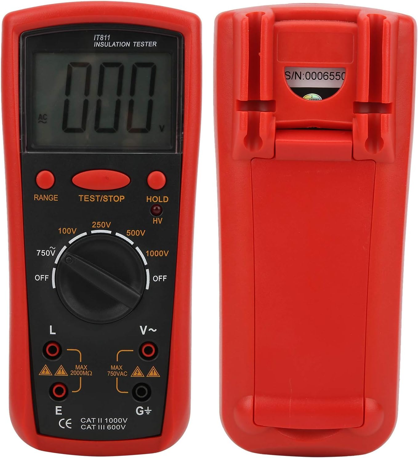
Figure 3: Front and back views of the EVTSCAN IT811, illustrating the input jacks and overall design.
6. Maintenance
6.1 Cleaning
Wipe the meter casing with a soft, damp cloth. Do not use abrasive cleaners or solvents. Ensure the meter is dry before storage or next use.
6.2 Battery Replacement
When the low battery indicator appears on the display, replace all six 1.5V AA batteries as described in Section 4.1. Remove batteries if the meter will not be used for an extended period to prevent leakage.
6.3 Storage
Store the meter in a cool, dry place, away from direct sunlight and extreme temperatures. Use the provided carrying bag for protection.
7. Troubleshooting
If you encounter issues with your EVTSCAN IT811, refer to the following common problems and solutions:
- Display shows '1' or 'OL': This indicates an over-range condition. The measured value exceeds the maximum range of the selected setting. Try a higher range if available, or verify the circuit condition.
- No display or faint display: The batteries may be low or incorrectly installed. Replace the batteries as per Section 4.1.
- Inaccurate readings: Check that the test leads are securely connected to both the meter and the circuit under test. Ensure the test leads are not damaged. Clean the input terminals if necessary.
- Meter does not turn on: Ensure batteries are correctly installed and have sufficient charge. Check that the rotary switch is moved from the 'OFF' position.
If the problem persists, contact EVTSCAN customer support for further assistance.
8. Specifications
| Feature | Specification |
|---|---|
| Display | 64x44mm LCD, Max Display "1999" |
| Over-Range Indication | Highest digit displays "1" |
| Power Supply | 6 x 1.5V Dry Battery (AA size) |
| Auto Power Off | Approx. 15 minutes after power on |
| Power Consumption | Test no-load power consumption <300mW |
| Use Environment | Temperature: 0℃-40℃, Relative Humidity: 30%RH-85%RH |
| Output Voltage | 100V / 250V / 500V / 1000V ±10% |
| Test Current (at specified R) | 100V (R=100kΩ): 1mA ±10% 250V (R=250kΩ): 1mA 500V (R=500kΩ): 1mA 1000V (R=1MΩ): 1mA |
| Insulation Resistance Range | 100V: 0.1MΩ-20MΩ ±(4% of Reading ±2 Digit) 250V: 0.1MΩ-20MΩ 500V: 0.1MΩ-50MΩ 1000V: 0.1MΩ-100MΩ Extended Ranges: 250V: 20MΩ-500MΩ 500V: 50MΩ-1000MΩ 1000V: 100MΩ-2000MΩ |
| Short Circuit Current | 100V: Approx. 1.2mA 250V/500V/1000V: Approx. 1.6mA |
| Median Resistance | 100V/250V/500V: 2 MΩ 1000V: 5MΩ |
| AC Voltage Measurement | AC750V ±(2% Reading + 5 Digit) |
| Jacks Location | Insulation Resistance: L, E AC750V: V~, G |
| AC750V Input Impedance | 1MΩ |
| AC750V Frequency Response | (50-200) Hz |
| Material | ABS |
| Item Weight | 770 g |
9. Warranty and Support
Specific warranty information for the EVTSCAN IT811 Insulation Resistance Meter is not provided in this manual. For details regarding warranty coverage, terms, and conditions, please refer to the product packaging or contact EVTSCAN customer support directly.
For technical assistance, troubleshooting beyond what is covered in this manual, or any other inquiries, please reach out to EVTSCAN customer service through their official website or the contact information provided with your purchase.