1. Introduction
This user manual provides detailed instructions for the installation, operation, and maintenance of the Atermiter X99 Dual CPU Motherboard. Designed for high-performance computing, this E-ATX motherboard features dual LGA 2011-3 sockets for Intel Xeon E5 V3 processors and eight DDR4 DIMM slots, supporting up to 256GB of RAM. Please read this manual thoroughly before proceeding with installation to ensure proper setup and avoid potential issues.
Key Features:
- High compatibility for a superior computing experience.
- Easy application and installation process.
- Constructed from high-quality, durable materials for stable operation.
- Features all solid capacitors for fine workmanship and professional stability.
2. Product Overview
The Atermiter X99 Dual CPU Motherboard is engineered for demanding workloads, offering robust support for dual Xeon processors and extensive memory configurations. Below are visual representations of the motherboard and its components.

Figure 2.1: Full top-down view of the Atermiter X99 Dual CPU Motherboard, showcasing its E-ATX form factor, dual LGA 2011-3 CPU sockets, eight DDR4 DIMM slots, multiple PCIe slots, and various connectors.

Figure 2.2: Angled view of the Atermiter X99 Dual CPU Motherboard, resting on red anti-static foam, highlighting the dual CPU sockets and the arrangement of the DDR4 memory slots.
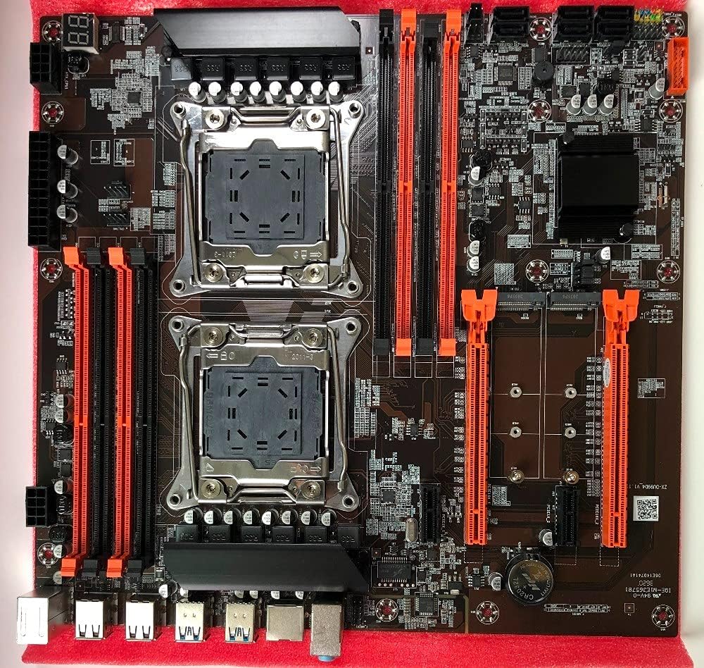
Figure 2.3: Another angled view of the Atermiter X99 Dual CPU Motherboard, similar to the previous, providing a clear perspective of the board's layout and component placement.
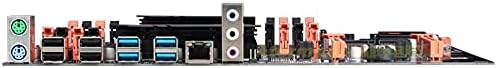
Figure 2.4: Close-up view of the rear I/O panel of the Atermiter X99 Dual CPU Motherboard, showing the various ports including USB, Ethernet, and audio jacks.
3. Specifications
The following table outlines the technical specifications of the Atermiter X99 Dual CPU Motherboard:
| Specification | Detail |
|---|---|
| Model Name | Atermiter X99 |
| Brand | RKRJJJ |
| CPU Socket | LGA 2011-v3 |
| Compatible Processors | Intel Xeon E5-2600 v3, Intel Xeon E5-1600 v3, Intel Xeon E5-1200 v3 |
| Chipset Type | Intel X99 |
| Structure | E-ATX |
| Memory Slots | 8 x DDR4 DIMM |
| RAM Memory Technology | DDR4 |
| Maximum Supported Memory | 256 GB (8 x 32GB DDR4) |
| Memory Clock Speed | 2133 MHz, 2400 MHz, 2666 MHz |
| Supported Memory Types | Non-ECC, REG ECC, ECC |
| Compatible Devices | Personal Computer |
| Platform | Linux (and other compatible OS) |
| USB Ports | USB 3.0 (various) |
| SATA Ports | SATA 3.0 (various) |
| M.2 Slots | Yes |
4. Setup Guide
Follow these steps carefully to install your Atermiter X99 Dual CPU Motherboard and its components.
4.1. Pre-Installation Checks
- Ensure you have an E-ATX compatible PC case.
- Verify your power supply unit (PSU) is sufficient. A minimum of 500W is recommended for stable operation with dual CPUs.
- Gather all necessary components: compatible CPUs, DDR4 RAM, storage devices (SATA/M.2), graphics card, and cooling solutions.
- Prepare a clean, static-free workspace. Use an anti-static wrist strap if available.
- Note: The CMOS battery may be removed for shipping purposes. Install a CR2032 battery if not present.
4.2. CPU Installation
- Gently open the CPU socket retention arm(s).
- Align the triangular mark on the CPU with the corresponding mark on the socket. Carefully place the CPU into the socket without forcing it.
- Close the retention arm(s) to secure the CPU.
- Apply a thin, even layer of thermal paste to the CPU's integrated heat spreader (IHS).
- Install the CPU cooler(s) according to its manufacturer's instructions.
4.3. RAM Installation
- Open the clips on both ends of the DDR4 DIMM slots.
- Align the notch on the RAM module with the key in the DIMM slot.
- Press down firmly on both ends of the RAM module until the clips snap into place.
- For optimal performance, install RAM modules in matched pairs or quads, following the motherboard's manual for specific slot population order (refer to the motherboard's silkscreen or a more detailed diagram if available).
4.4. Storage Device Installation (M.2 / SATA)
- M.2 SSD: Insert the M.2 SSD into the M.2 slot at an angle, then gently push it down and secure it with the provided screw.
- SATA Drives: Connect SATA data cables from your storage drives (HDDs/SSDs) to the SATA ports on the motherboard. Connect power cables from your PSU to the drives.
4.5. Power Connections
- Connect the 24-pin ATX power connector from your PSU to the corresponding port on the motherboard.
- Connect the 8-pin (or 4+4 pin) CPU power connector(s) to the motherboard. This motherboard requires power for both CPUs.
- Connect any additional power connectors required for your graphics card(s) or other components.
4.6. Front Panel and Peripheral Connections
- Connect the front panel headers (Power SW, Reset SW, HDD LED, Power LED) to the motherboard. Refer to the motherboard's silkscreen for correct pin alignment.
- Connect USB 2.0 and USB 3.0 front panel headers.
- Connect the front panel audio header.
- Install your graphics card(s) into the appropriate PCIe slots and secure them.
- Install any other expansion cards (e.g., network cards, sound cards) as needed.
5. Operating Instructions
5.1. First Boot
- After all components are installed and connected, ensure all cables are secure.
- Connect your monitor, keyboard, and mouse.
- Turn on the power supply and then press the power button on your PC case.
- The system should power on and display the BIOS/UEFI splash screen.
5.2. BIOS/UEFI Configuration
- During startup, press the designated key (usually DEL, F2, or F10) to enter the BIOS/UEFI setup utility.
- Configure boot order, enable/disable integrated peripherals, and adjust system settings as required.
- Save changes and exit the BIOS/UEFI. The system will restart.
5.3. Operating System and Driver Installation
- Insert your operating system installation media (USB drive or DVD).
- Follow the on-screen prompts to install your preferred operating system.
- After OS installation, install the necessary drivers for the motherboard chipset, graphics card, audio, and network. These are typically found on the manufacturer's website or an included driver disc.
6. Maintenance
Regular maintenance helps ensure the longevity and stable performance of your motherboard.
- Dust Removal: Periodically clean dust from the motherboard, CPU coolers, and case fans using compressed air. Ensure the system is powered off and unplugged before cleaning.
- BIOS Updates: Check the manufacturer's website for BIOS/UEFI updates. Updates can improve compatibility, stability, and performance. Follow the update instructions carefully to avoid damaging the motherboard.
- Cable Management: Ensure internal cables are neatly routed to improve airflow and prevent interference.
7. Troubleshooting
This section addresses common issues you might encounter with the Atermiter X99 Dual CPU Motherboard.
7.1. Common Issues and Solutions
- No Power / System Not Starting:
- Ensure all power cables (24-pin ATX, 8-pin CPU) are securely connected.
- Verify your power supply unit (PSU) is at least 500W and functioning correctly.
- Check front panel power switch connections.
- No Display Output:
- Ensure the graphics card is properly seated in its PCIe slot and has adequate power.
- Check monitor cable connections.
- Try reseating RAM modules.
- System Instability / Crashes:
- CPU Compatibility: Ensure both installed CPUs are of the same core number combination. Mixed core numbers (e.g., 4 cores + 6 cores, or 6 cores + 8 cores) are not supported and will cause instability.
- Memory Compatibility: Server memory (REG ECC/ECC) cannot be mixed with desktop memory (Non-ECC). Ensure all installed RAM modules are of the same type. Compatibility issues may arise if mixed.
- Check CPU and GPU temperatures. Ensure cooling solutions are properly installed.
- Verify PSU stability under load.
- Peripheral Not Detected:
- Ensure the device is properly connected.
- Install the latest drivers for the device and motherboard chipset.
- Check BIOS/UEFI settings to ensure the port/controller is enabled.
8. Important Notes and Warnings
- Power Supply: This motherboard requires a powerful power supply. Ensure your PSU is sufficient to support this configuration (at least 500W).
- CMOS Battery: The battery in the motherboard photos will be removed before shipment due to postal and customs regulations. Please install a CR2032 battery upon receipt if not present.
- Product Appearance: New and old models may be shipped randomly, and the appearance of the motherboard may vary slightly between different production batches. This does not affect functionality.
- Measurement Tolerance: Due to manual measurement, a difference of 1-3mm in dimensions is allowed.
- Color Representation: Due to variations in screens and lighting, the picture may not perfectly show the actual color of the item.
9. Warranty and Support
For technical support, troubleshooting assistance beyond this manual, or warranty inquiries, please contact your retailer or the manufacturer directly. Keep your proof of purchase for any warranty claims.
For general inquiries or to find updated drivers and support resources, please visit the official RKRJJJ support website (if available).


