1. Introduction
The Virone DM-1 is a portable digital multimeter designed for precise and professional measurement of various electrical parameters. It features an LCD display, a rotary selector for function and range selection, overload protection, and a low battery indicator. This manual provides essential information for safe and effective use of your DM-1 multimeter.
2. Safety Information
WARNING: Always observe safety precautions when working with electrical circuits. Failure to do so may result in injury or damage to the device.
- Ensure the multimeter is in good working condition before use.
- Do not attempt to measure voltages or currents exceeding the specified maximum limits.
- Always disconnect power to the circuit before making resistance, diode, or transistor measurements.
- The device features an integrated fuse for overload protection. Do not bypass or replace with an incorrect fuse type.
- Avoid contact with live circuits. Use only the provided test leads.
- If the low battery indicator appears, replace the battery promptly to ensure accurate readings.
- This device complies with relevant safety standards.
3. Product Components
The Virone DM-1 Digital Multimeter package typically includes the following items:
- Virone DM-1 Digital Multimeter
- Test Leads (Red and Black)
- 9V Battery (pre-installed or included)
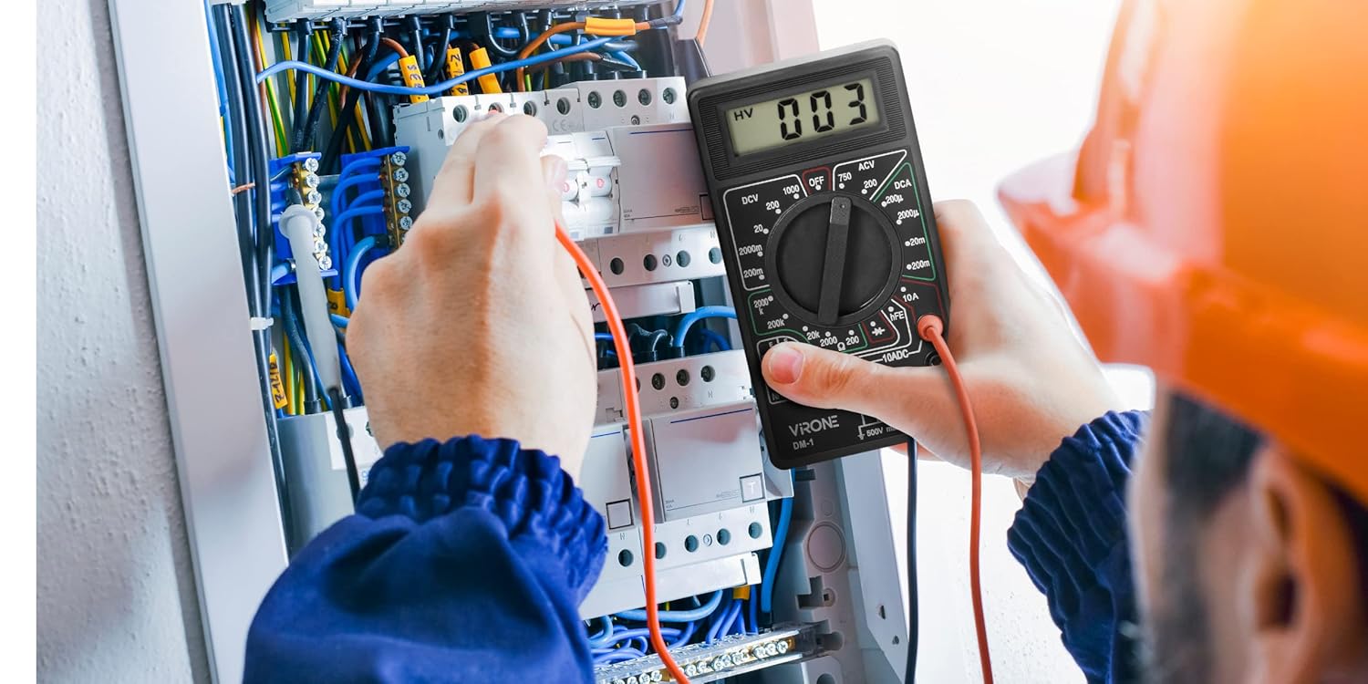
Figure 3.1: Front view of the Virone DM-1 Digital Multimeter, showing the LCD display, rotary selector, and input jacks.

Figure 3.2: Red and black test leads used for connecting the multimeter to circuits.
4. Setup
4.1 Battery Installation/Replacement
The Virone DM-1 multimeter requires one 9V DC battery for operation. The battery is typically pre-installed. If the low battery indicator appears on the LCD, or if the device does not power on, the battery needs to be replaced.
- Ensure the multimeter is turned OFF.
- Locate the battery compartment on the back of the device. This may require unscrewing the back panel.
- Carefully remove the screws securing the back panel and lift it off.
- Disconnect the old 9V battery from its terminals.
- Connect a new 9V battery, observing correct polarity (+ to + and - to -).
- Replace the back panel and secure it with the screws.

Figure 4.1: Back view of the multimeter, indicating the location of the battery compartment.
4.2 Connecting Test Leads
Connect the test leads to the appropriate input jacks on the multimeter:
- Insert the black test lead into the "COM" (Common) jack.
- For most measurements (Voltage, Resistance, Diode, Transistor hFE, and small DC Current), insert the red test lead into the "VΩmA" jack.
- For measuring high DC Current (up to 10A), insert the red test lead into the "10A" jack. Ensure the rotary selector is set to the 10A range.
5. Operating Instructions
To operate the Virone DM-1, turn the rotary selector to the desired function and range. The measured value will be displayed on the LCD screen.
5.1 Measuring DC Voltage (DCV)
- Connect the red test lead to the "VΩmA" jack and the black test lead to the "COM" jack.
- Set the rotary selector to the desired "DCV" range (e.g., 200m, 2000m, 20, 200, 1000). Start with the highest range if the voltage is unknown.
- Connect the test probes across the component or circuit where you want to measure voltage.
- Read the voltage value on the LCD.
5.2 Measuring AC Voltage (ACV)
- Connect the red test lead to the "VΩmA" jack and the black test lead to the "COM" jack.
- Set the rotary selector to the desired "ACV" range (e.g., 200, 750). Start with the highest range if the voltage is unknown.
- Connect the test probes across the AC voltage source.
- Read the voltage value on the LCD.
5.3 Measuring DC Current (DCA)
CAUTION: To measure current, the multimeter must be connected in series with the circuit. Never connect the multimeter in parallel with a voltage source when in current mode, as this can damage the device and the circuit.
- For currents up to 200mA, connect the red test lead to the "VΩmA" jack. For currents up to 10A, connect the red test lead to the "10A" jack. Connect the black test lead to the "COM" jack.
- Set the rotary selector to the desired "DCA" range (e.g., 200μ, 2000μ, 20m, 200m, 10A).
- Open the circuit where you want to measure current and connect the multimeter in series.
- Read the current value on the LCD.
5.4 Measuring Resistance (Ω)
WARNING: Ensure the circuit is completely de-energized before measuring resistance. Measuring resistance on a live circuit can damage the multimeter.
- Connect the red test lead to the "VΩmA" jack and the black test lead to the "COM" jack.
- Set the rotary selector to the desired "Ω" (Ohms) range (e.g., 200, 2000, 20k, 200k, 2000k).
- Connect the test probes across the component whose resistance you want to measure.
- Read the resistance value on the LCD.
5.5 Diode Test
- Connect the red test lead to the "VΩmA" jack and the black test lead to the "COM" jack.
- Set the rotary selector to the diode symbol (→|→).
- Connect the red probe to the anode and the black probe to the cathode of the diode. The display will show the forward voltage drop.
- Reverse the probes. The display should show "OL" (Overload) for a good diode.
5.6 Transistor hFE Test
- Set the rotary selector to the "hFE" position.
- Identify if the transistor is NPN or PNP.
- Insert the transistor leads (Emitter, Base, Collector) into the corresponding holes in the hFE socket on the multimeter.
- Read the hFE value (DC current gain) on the LCD.

Figure 5.1: The Virone DM-1 Multimeter in use, demonstrating its application in electrical measurements.
6. Maintenance
6.1 Cleaning
Wipe the device with a dry, soft cloth. Do not use abrasive cleaners or solvents.
6.2 Storage
When not in use for extended periods, turn the multimeter OFF and remove the 9V battery to prevent leakage and damage. Store the device in a cool, dry place, away from direct sunlight and extreme temperatures.
7. Troubleshooting
- No Display / Device Not Powering On:
- Check if the 9V battery is correctly installed.
- Replace the 9V battery if it is depleted (indicated by the low battery symbol).
- Incorrect Readings:
- Ensure the test leads are properly connected to the correct input jacks.
- Verify that the rotary selector is set to the appropriate function and range for the measurement.
- Check the battery level; a low battery can affect accuracy.
- Overload Indication ("OL"):
- The measured value exceeds the selected range. Switch to a higher range.
- In resistance mode, "OL" can indicate an open circuit.
- In diode test, "OL" for reverse bias is normal for a good diode.
- No Continuity Beep (if applicable):
- This model does not feature an audible continuity indicator.
8. Specifications
| Feature | Detail |
|---|---|
| Brand | Virone |
| Model | DM-1 |
| Power Supply | 1 x 9V DC Battery |
| Low Battery Indicator | Yes |
| Overload Protection | Yes (Integrated Fuse) |
| Display | LCD |
| Dimensions (W x H x D) | 69 x 124 x 22 mm (approx. 2.7 x 4.9 x 0.9 inches) |
| Weight | 140 Grams (approx. 4.9 oz) |
| AC Voltage Measurement | Yes |
| DC Voltage Measurement | Yes |
| DC Current Measurement | Yes |
| Resistance Measurement | Yes |
| Diode Test | Yes |
| Transistor hFE Test | Yes |
| Safety Standards | Complies with relevant safety standards |
9. Warranty and Support
Information regarding specific warranty terms or direct customer support contacts is not provided in the product details. Please refer to your point of purchase or the manufacturer's official website for warranty claims or technical assistance.


