
1. Introduction
This manual provides essential information for the safe and efficient installation, operation, and maintenance of your U.S. Solid Motorized Ball Valve. Please read these instructions thoroughly before installation and retain this manual for future reference. This valve is designed for various applications requiring automated fluid control, featuring a durable stainless steel construction and a 2-wire auto return setup.
2. Safety Information
- Always disconnect power before installing, servicing, or performing any maintenance on the valve.
- Ensure all electrical connections comply with local codes and regulations.
- Wear appropriate personal protective equipment (PPE) during installation and maintenance.
- Verify the voltage supply matches the valve's specifications (9-24V AC/DC).
- Do not exceed the maximum operating pressure of 10 bars (145 PSI).
- Avoid installing the valve in locations subject to extreme temperatures or corrosive environments beyond its IP65 rating.
3. Product Overview
3.1 Key Features
- Material: Constructed from 304 stainless steel for durability and reliability.
- Port Size: 3/4" NPT threading with a full port design to minimize pressure loss.
- Voltage: Operates on 9-24V AC/DC.
- Operation: Opens or closes in 3-5 seconds.
- Wiring: Simple 2-wire automatic return setup.
- Safety: Limit switch minimizes power consumption once fully open or closed, reducing overheating risk.
- Protection: IP65 rated for dust-tight and water jet protection.
3.2 Components
The U.S. Solid Motorized Ball Valve consists of two primary components: the stainless steel ball valve body and the motorized actuator unit. The actuator houses the motor, gearing, and control electronics.
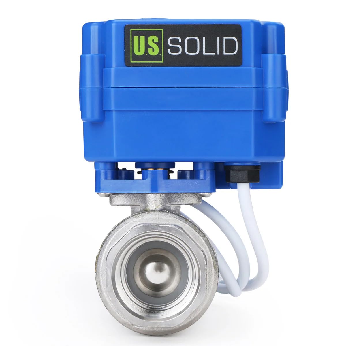
Figure 1: Front view of the U.S. Solid Motorized Ball Valve, showing the blue actuator and stainless steel valve body.
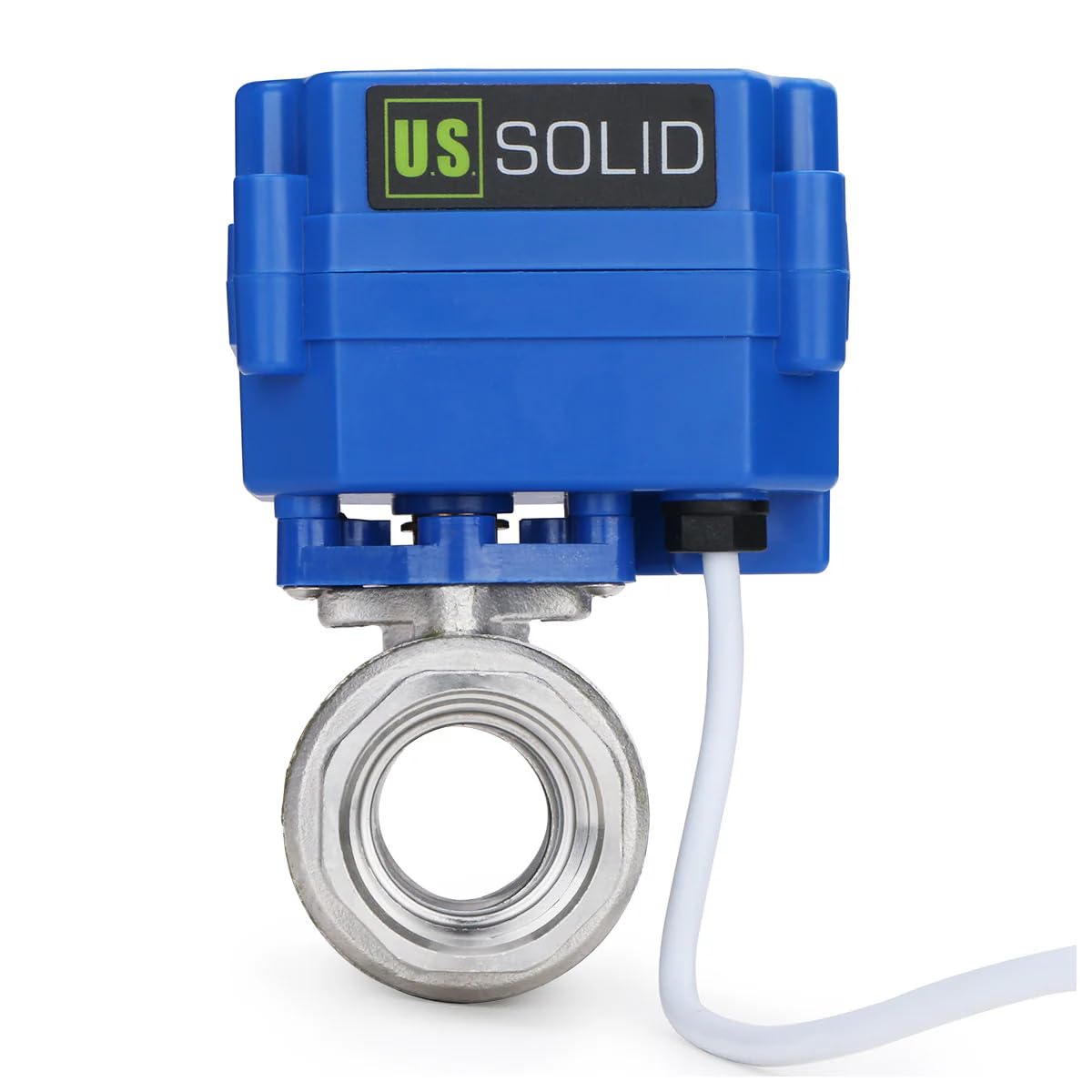
Figure 2: Side view of the valve, illustrating the compact design of the actuator and the threaded valve connections.

Figure 3: Internal view of the actuator's circuit board, showing electronic components and wiring connections.
3.3 Specifications
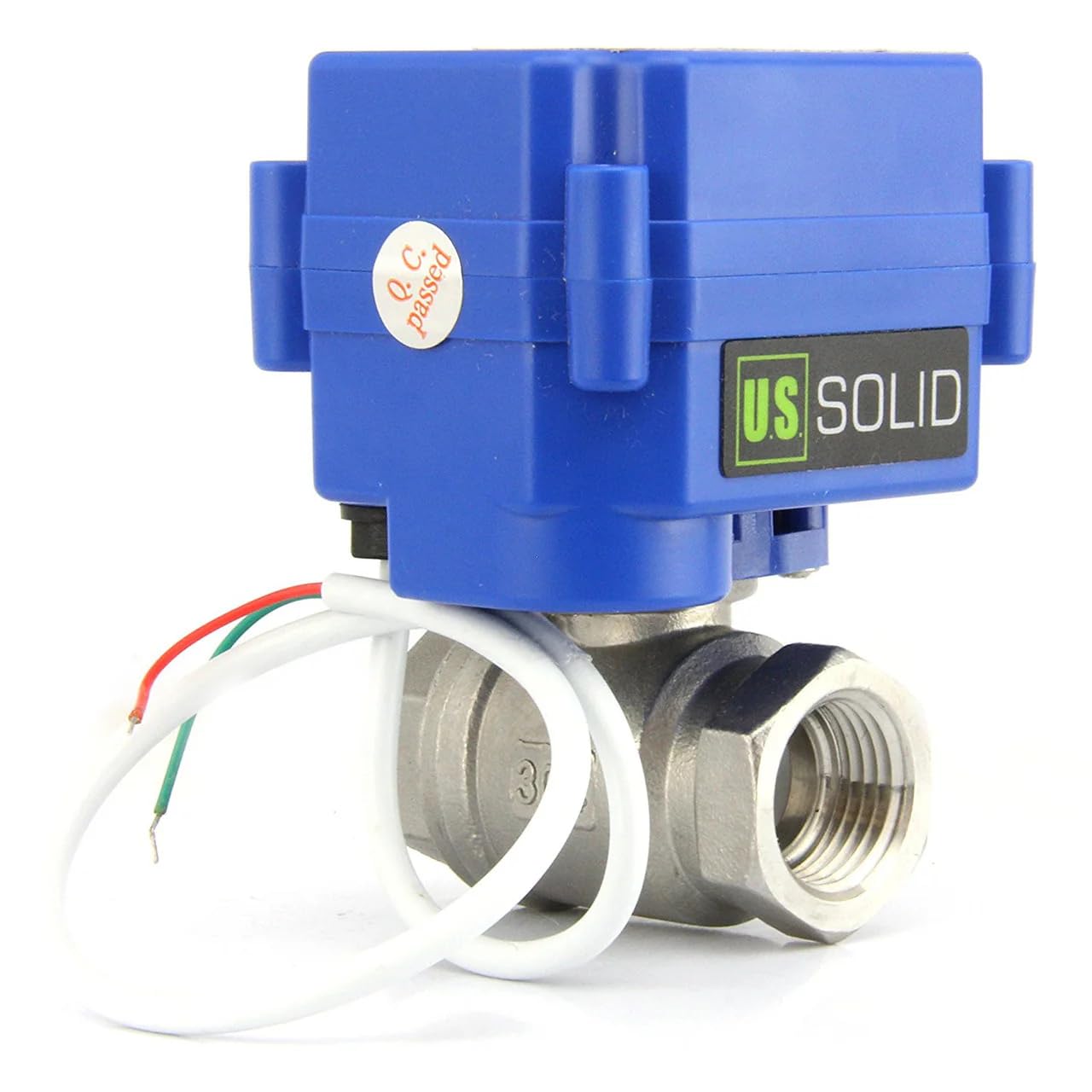
Figure 4: Product dimensions, showing approximate measurements of the valve and actuator assembly.
| Specification | Value |
|---|---|
| Model Number | USS-MSV00072 |
| Material | Stainless Steel (304) |
| Size | 0.75 Inch (3/4") |
| Inlet/Outlet Connection Size | 3/4 Inches |
| Inlet/Outlet Connection Type | National Pipe Tapered (NPT) |
| Voltage | 9-24V AC/DC |
| Maximum Operating Pressure | 10 Bars (145 PSI) |
| Number of Ports | 2 |
| Actuation Time | 3-5 seconds |
| Life Expectancy | 80,000 to 100,000 cycles |
| Protection Rating | IP65 |
| Item Weight | 12.7 ounces |
| Product Dimensions (L x W x H) | 3.66 x 2.68 x 2.48 inches |

Figure 5: Explanation of the IP65 ingress protection rating, indicating dust-tightness and protection against water jets.
4. Setup and Installation
4.1 Mechanical Installation
- Ensure the system is depressurized and drained before installation.
- Apply PTFE (Teflon) tape to the male pipe threads to ensure a watertight seal. Wrap the tape clockwise around the threads, typically 3-5 layers.
- Screw the valve firmly into the piping system. Do not overtighten, as this can damage the threads or valve body.
- Ensure the valve is installed in an accessible location for future maintenance.

Figure 6: Illustration of applying Teflon tape to male pipe threads for a secure, leak-free connection.
4.2 Electrical Wiring (2-Wire Auto Return Setup)
This valve features a 2-wire auto return setup, meaning it will return to its fully open position if power is removed. It is a Normally Open (NO) valve, which means it is open when no power is applied.
- For DC Power: Connect the red wire to the positive (+) terminal and the black wire to the negative (-) terminal of your 9-24V DC power supply. Applying power will close the valve. Removing power will cause the valve to automatically return to its open position.
- For AC Power: Connect the red wire to one AC line and the black wire to the other AC line of your 9-24V AC power supply. Applying power will close the valve. Removing power will cause the valve to automatically return to its open position.

Figure 7: Wiring diagram for the 2-wire auto return setup, illustrating connections for both DC and AC power sources.
5. Operation
The U.S. Solid Motorized Ball Valve is designed for simple on/off control. As a Normally Open (NO) valve, its default state without power is open.
- To Close the Valve: Apply 9-24V AC/DC power to the red and black wires. The actuator will rotate, closing the ball valve. Once fully closed, an internal limit switch will cut power to the motor, preventing overheating.
- To Open the Valve: Remove the 9-24V AC/DC power from the red and black wires. The actuator will automatically return to its original position, opening the ball valve.
Figure 8: Diagram illustrating the 'Normally Open' operation, showing the valve's state with and without power.
6. Maintenance
The U.S. Solid Motorized Ball Valve is designed for minimal maintenance. Regular inspection can help ensure long-term reliable operation.
- Periodic Inspection: Visually inspect the valve and actuator for any signs of damage, corrosion, or leaks. Check electrical connections for tightness and integrity.
- Cleaning: If necessary, clean the exterior of the valve and actuator with a damp cloth. Do not use harsh chemicals or abrasive cleaners. Ensure no water enters the actuator housing.
- Actuator Check: Periodically cycle the valve (open and close) to ensure smooth operation. Listen for any unusual noises during actuation.
7. Troubleshooting
If you encounter issues with your motorized ball valve, refer to the following troubleshooting guide:
| Problem | Possible Cause | Solution |
|---|---|---|
| Valve does not actuate (open/close) | No power or incorrect voltage Loose wiring connection Motor malfunction | Verify power supply (9-24V AC/DC) and connections. Check for secure wiring. Ensure correct polarity for DC. If power is present and connections are secure, the motor may be faulty. Contact support. |
| Valve does not fully open or close | Obstruction in valve Insufficient power Internal gear damage (as noted in some user experiences) | Inspect the valve for debris. Ensure adequate power supply. If the issue persists, the internal mechanism may be damaged. Contact support. |
| Valve leaks | Improperly sealed threads Damaged valve body or seals | Ensure PTFE tape was applied correctly and connections are tight. If the leak is from the valve body itself, the valve may be damaged and require replacement. |
| Actuator makes unusual noise | Internal gear wear or damage | This may indicate internal wear. Monitor operation; if performance degrades, consider replacement. |
8. Warranty and Support
U.S. Solid offers a 1-year warranty or money-back promise on its products, ensuring customer satisfaction. For technical support, warranty claims, or further assistance, please visit the official U.S. Solid store or contact their customer service department.
U.S. Solid Store: https://www.amazon.com/stores/USSolid/page/29AB675D-2238-4826-BDE2-09EFEAB81AA6