1. Introduction
The ANENG AN8205 is a versatile digital multimeter designed for a wide range of electrical measurements. It is capable of measuring AC and DC voltage, DC current, resistance, and performing audible continuity and diode/transistor verification tests. Its compact design and clear digital display make it suitable for both professional and DIY electrical tasks.

Figure 1.1: The ANENG AN8205 Multimeter, highlighting its portable and compact design.
Key features include overload protection, low battery voltage indication, and a data hold function for convenient readings. This manual provides essential information for the safe operation, setup, and maintenance of your multimeter.
2. Safety Information
WARNING: To avoid electrical shock, remove test leads before opening the case. Please read this manual thoroughly for safety instructions before operation.

Figure 2.1: Rear view of the multimeter, displaying important safety warnings and the kickstand.
- Always ensure the multimeter is set to the correct range and function before making measurements.
- Do not attempt to measure voltages or currents exceeding the specified maximum limits.
- Exercise extreme caution when working with live circuits. Always assume circuits are live until proven otherwise.
- Inspect test leads for damage before each use. Do not use if insulation is cracked or if the probes are exposed.
- Replace the battery when the low battery indicator appears to ensure accurate readings.
- Do not operate the multimeter if it appears damaged or if the case is open.
3. Product Overview
The ANENG AN8205 multimeter features a clear LCD display, a rotary switch for function selection, and multiple input jacks for test leads.

Figure 3.1: Front panel of the ANENG AN8205 Multimeter, detailing the display, rotary switch, and input terminals.
3.1 Components
- LCD Display: Shows measurement readings, units, and indicators (e.g., low battery, data hold). Maximum display: 1999.
- Rotary Switch: Used to select the desired measurement function and range. It has 20 positions.
- Input Jacks:
- COM (Common): Negative input for all measurements.
- VΩmA: Positive input for voltage, resistance, and current measurements up to 200mA.
- 10ADC: Positive input for DC current measurements up to 10A (unfused).
- HOLD Button: Freezes the current reading on the display.
- BACK LIGHT Button: Activates the blue backlight for improved visibility in low-light conditions.
- Kickstand: Located on the back for hands-free operation.
4. Setup
4.1 Battery Installation
The AN8205 multimeter requires one 6F22 9V battery (not included). To install or replace the battery:
- Ensure the multimeter is turned OFF and disconnect all test leads.
- Locate the battery compartment cover on the back of the unit.
- Remove the screw securing the cover (if present) and open the compartment.
- Connect a new 9V battery to the battery clip, observing correct polarity.
- Place the battery inside the compartment and replace the cover, securing it with the screw.
4.2 Connecting Test Leads
The multimeter comes with two testing cables (red and black). To connect them:
- Insert the black test lead into the COM (Common) jack.
- For most measurements (voltage, resistance, continuity, diode, and current up to 200mA), insert the red test lead into the VΩmA jack.
- For high DC current measurements (up to 10A), insert the red test lead into the 10ADC jack.

Figure 4.1: Multimeter with test leads connected, ready for use.
5. Operating Instructions
Before taking any measurement, ensure the test leads are correctly connected and the rotary switch is set to the appropriate function and range.
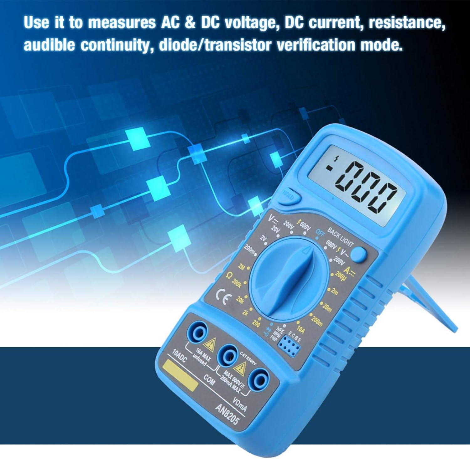
Figure 5.1: The multimeter being used to measure AC & DC voltage, DC current, resistance, audible continuity, or diode/transistor verification.
5.1 Measuring DC Voltage (V–)
- Connect the black lead to COM and the red lead to VΩmA.
- Set the rotary switch to the desired DC Voltage (V–) range (e.g., 200mV, 2V, 20V, 200V, 600V). If the voltage is unknown, start with the highest range and decrease as needed.
- Touch the test probes to the circuit points where you want to measure the voltage.
- Read the voltage value on the LCD display.
5.2 Measuring AC Voltage (V∼)
- Connect the black lead to COM and the red lead to VΩmA.
- Set the rotary switch to the desired AC Voltage (V∼) range (e.g., 200V, 600V).
- Touch the test probes to the circuit points.
- Read the voltage value on the LCD display.
5.3 Measuring DC Current (A–)
- Connect the black lead to COM. For currents up to 200mA, connect the red lead to VΩmA. For currents up to 10A, connect the red lead to 10ADC.
- Set the rotary switch to the desired DC Current (A–) range (e.g., 200uA, 2mA, 20mA, 200mA, 10A).
- Open the circuit where you want to measure current and connect the multimeter in series with the load.
- Read the current value on the LCD display.
5.4 Measuring Resistance (Ω)
- Connect the black lead to COM and the red lead to VΩmA.
- Set the rotary switch to the desired Resistance (Ω) range (e.g., 200Ω, 2kΩ, 20kΩ, 200kΩ, 2MΩ).
- Ensure the circuit or component is de-energized before measuring resistance.
- Touch the test probes across the component.
- Read the resistance value on the LCD display.
5.5 Audible Continuity Test
- Connect the black lead to COM and the red lead to VΩmA.
- Set the rotary switch to the continuity symbol (usually indicated by a speaker icon).
- Touch the test probes to the two points of the circuit or component you want to test.
- If there is continuity (a low resistance path), the multimeter will emit an audible beep. The display will show the resistance value.
5.6 Diode/Transistor Verification Mode
- Connect the black lead to COM and the red lead to VΩmA.
- Set the rotary switch to the diode symbol (usually indicated by a diode icon).
- For diode test, touch the red probe to the anode and the black probe to the cathode. The display will show the forward voltage drop. Reverse the probes; the display should show 'OL' (open loop) for a good diode.
- For transistor (hFE) test, insert the transistor leads into the appropriate hFE sockets (NPN or PNP) on the multimeter. The display will show the hFE value.
5.7 Data Hold Function
Press the HOLD button to freeze the current reading on the display. Press it again to release the hold and resume live measurements.
5.8 Backlight Function
Press the BACK LIGHT button to turn on the blue backlight. This improves visibility in dimly lit environments. Press it again to turn off the backlight.
6. Maintenance
6.1 Cleaning
Wipe the case with a damp cloth and mild detergent. Do not use abrasives or solvents. Keep the input terminals free from dirt and moisture.
6.2 Battery Replacement
When the low battery indicator appears on the display, replace the 9V battery as described in Section 4.1. Remove the battery if the multimeter is not used for an extended period to prevent leakage.
7. Troubleshooting
- No display or faint display: Check battery installation and replace if necessary. Ensure the multimeter is turned ON.
- Incorrect readings:
- Ensure the test leads are correctly connected to the appropriate input jacks.
- Verify the rotary switch is set to the correct function and range for the measurement.
- Check for damaged test leads.
- Ensure the battery is not low.
- "OL" (Overload) displayed: The measured value exceeds the selected range. Switch to a higher range or ensure the circuit is within the multimeter's capabilities.
- No continuity beep: Check if the circuit is truly continuous. Ensure test leads are making good contact.
8. Specifications
| Parameter | Value |
|---|---|
| Model Number | AN8205 |
| Material | ABS |
| Display Type | Digital Display |
| Maximum Display | 1999 |
| DC Voltage Range | 200mV - 2-20-200-600V |
| AC Voltage Range | 200mV-600V |
| DC Current Range | 200u-2m-20m-200m-10A |
| Resistance Range | 200-2k-20k-200k-2MΩ |
| Battery Type | 6F22 9V Battery (Not Included) |
| Buzzer Test | Yes |
| Night Light | Blue |
| Operating Mode | Manual Mode |
| Dimensions (L x W x H) | Approx. 13.5 x 6.5 x 3cm / 5.31 x 2.55 x 1.18inch |
| Weight | 123g / 4.34oz |
9. Warranty and Support
Warranty information for the ANENG AN8205 Digital Multimeter is typically provided at the point of purchase or included with the product packaging. Please refer to your purchase documentation for specific warranty terms and conditions.
For technical support, service, or inquiries regarding your product, please contact the manufacturer, EVTSCAN, or your authorized reseller. Contact details can usually be found on the product packaging or the manufacturer's official website.