
DieseRC B098T1XDW8
DieseRC Universal Wireless Remote Control Switch User Manual
Model: B098T1XDW8
Product Overview
This manual provides instructions for the DieseRC Universal Wireless Remote Control Switch, a versatile 4-channel RF relay receiver board designed for controlling various electrical devices such as garage doors, lights, motors, and electric curtains. It operates on AC 110V-240V and features stable and reliable performance with high reception sensitivity.

Figure 1: DieseRC Universal Wireless Remote Control Switch components, including the receiver board and two 4-button remote controls.
Key Features
- Wide Voltage Compatibility: Operates with AC 85V to 240V, offering flexible application.
- High Power Capacity: High-quality relays can handle up to 15A current, ensuring durability and stable operation.
- Extended Range: RF 433MHz wireless control provides strong signal penetration through walls, floors, and doors, with a control distance of up to 50 meters without obstacles.
- Multiple Operating Modes: Supports Momentary, Toggle, and Latched modes, configurable to suit various control needs.
- Multi-Device Control: Each receiver can store up to 20 transmitters, and one transmitter can control multiple receivers.

Figure 2: The remote control offers a range of up to 50 meters, providing convenient control throughout your home.
Product Components
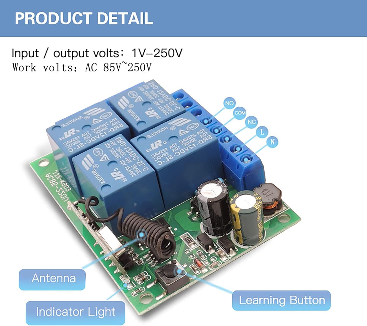
Figure 3: Detailed view of the receiver board, highlighting the antenna, indicator light, learning button, and input/output terminals (NO, COM, NC, L, N).

Figure 4: Detailed view of the remote control, featuring silicone buttons for comfortable use, an indicator light, and a durable metal keychain with a chrome bezel.
Setup and Wiring
The receiver board supports input/output voltages from 1V to 250V and operates with AC 85V to 250V. Each of the four relays has Normally Open (NO), Common (COM), and Normally Closed (NC) terminals, allowing for independent control of connected devices.

Figure 5: Wiring diagram illustrating connections for input power (AC 85V-250V) and output to devices via NO, COM, and NC terminals. Ensure correct polarity and voltage for your application.
Wiring Examples:

Figure 6: Various wiring configurations for common applications such as AC motors, DC motors, and lighting systems. Always consult a qualified electrician if unsure about wiring.
Operating Modes and Programming
The DieseRC remote control switch supports multiple operating modes, allowing for flexible control of your devices. Programming involves pressing the learning button on the receiver board a specific number of times, then pressing a button on the remote control.
Programming Instructions Video:
Video 1: This video demonstrates how to program the remote control switch for different operating modes, including Momentary, Toggle, and Latched modes, as well as mixed modes. It shows the steps for pairing the remote with the receiver.
1. Momentary Mode (Mode 1)
In Momentary mode, the relay remains active only as long as the remote button is pressed. Releasing the button deactivates the relay.
- Press the learning button on the receiver board 1 time. The indicator light will turn on.
- Press any button on the remote control. The indicator light on the receiver will flash, confirming successful pairing.

Figure 7: Visual representation of Momentary Mode (top row), where the light turns on only while the button is pressed.
2. Toggle Mode (Mode 2)
In Toggle mode, pressing the remote button once activates the relay, and it remains active until the same button is pressed again to deactivate it.
- Press the learning button on the receiver board 2 times. The indicator light will turn on.
- Press any button on the remote control. The indicator light on the receiver will flash, confirming successful pairing.
Figure 7 (middle row): Visual representation of Toggle Mode, where one press turns the light on, and another press turns it off.
3. Latched Mode (Mode 3)
In Latched mode, pressing one button on the remote activates a relay, and it remains active until another button on the same remote is pressed to deactivate it. Only one relay can be active at a time in this mode.
- Press the learning button on the receiver board 3 times. The indicator light will turn on.
- Press any button on the remote control. The indicator light on the receiver will flash, confirming successful pairing.
Figure 7 (bottom row): Visual representation of Latched Mode, where pressing button 'A' turns on Relay 1, and pressing button 'B' turns on Relay 2 while turning off Relay 1.
Resetting the Receiver
To clear all programmed remote controls from the receiver, follow these steps:
- Press the learning button on the receiver board 8 times.
- The indicator light will flash rapidly and then turn off, indicating that all stored remote controls have been cleared.

Figure 8: Resetting the receiver by pressing the learning button eight times. This clears all previously paired remote controls.
Applications
This versatile RF relay module can be widely used in various settings, providing remote control for a multitude of devices.

Figure 9: Examples of common applications for the RF relay module, such as controlling garage doors, lighting, electric curtains, gates, and electric fans.
Garage Door Control Example:
Video 2: This video demonstrates the use of the relay remote control switch for operating a garage door, showcasing its practical application in a home setting.
Specifications
| Feature | Specification |
|---|---|
| Brand | DieseRC |
| Model Number | B098T1XDW8 |
| Connector Type | Through Hole |
| Contact Type | Normally Closed |
| Current Rating | 10 Amps |
| Mounting Type | PCB Mount |
| Operation Mode | Toggle Mode (Adjustable to Momentary/Latched) |
| Coil Voltage | 240 Volts |
| Maximum Switching Voltage | 240 Volts |
| Minimum Switching Voltage | 240 Volts (AC) |
| UPC | 750828381330 |
| Item Weight | 5.9 ounces |
| Batteries | 1 CR2032 batteries required (included) |
| Date First Available | June 14, 2022 |
| Manufacturer | DieseRC |
Troubleshooting
If you encounter issues with your DieseRC remote control switch, consider the following common troubleshooting steps:
- Remote Not Responding:
- Check the remote control battery (CR2032). Replace if necessary.
- Ensure the receiver is powered on and correctly wired.
- Reprogram the remote control to the receiver following the "Operating Modes and Programming" instructions.
- Verify that the remote is within the effective operating range (up to 50 meters without obstacles).
- Relay Not Activating/Deactivating Correctly:
- Confirm the operating mode (Momentary, Toggle, Latched) is correctly set for your application. Refer to the programming section.
- Check the wiring connections to the device and ensure they are secure and correct (NO, COM, NC).
- Ensure the connected device is within the current and voltage limits of the relay (10A, 240V).
- Interference:
- Strong electromagnetic interference can affect performance. Try relocating the receiver or reducing sources of interference.
- Receiver Indicator Light Behavior:
- If the light does not respond during programming, ensure the learning button is pressed correctly and for the appropriate duration.
- If the light is constantly on or off unexpectedly, try resetting the receiver (press 8 times) and then reprogramming.
Warranty and Support
DieseRC is committed to providing high-quality products and excellent after-sales service. For any questions, technical assistance, or warranty claims, please contact DieseRC customer support.
- Manufacturer: DieseRC
- User Manual (PDF): A detailed user manual in PDF format is available for download. Download PDF Manual
- After-Sales Service: DieseRC strives to provide perfect after-sales service to resolve any customer issues.
Related documentsB098T1XDW8


Ask a question about this manual
Ask about setup, troubleshooting, compatibility, parts, safety, or missing instructions. Manuals+ will review the question and use this page’s manual context to help answer it.