
1. Introduction
Thank you for choosing the Kamoer AIP Intelligent Peristaltic Pump. This device is designed for precise liquid dosing and transfer in various applications, offering advanced control options including WiFi connectivity and a touch screen interface. This manual provides essential information for the safe and efficient operation of your pump. Please read it thoroughly before use and retain it for future reference.
2. Safety Information
- Always connect the pump to a grounded power outlet with the specified voltage (100V-240V).
- Do not operate the pump with damaged power cords or plugs.
- Ensure proper ventilation around the pump to prevent overheating.
- Avoid exposing the pump to water or other liquids, except for the intended fluid transfer through the tubing.
- Wear appropriate personal protective equipment (PPE) when handling chemicals or hazardous liquids.
- Keep the pump out of reach of children and unauthorized personnel.
- Disconnect power before performing any maintenance or cleaning.
3. Product Overview
The Kamoer AIP pump features a robust design with a user-friendly interface for precise control.

Figure 3.1: This image displays the Kamoer AIP peristaltic pump from the front-right angle, showcasing its compact design, the integrated touch screen display, and the transparent pump head (KK25) with tubing.
3.1 Front Panel Controls

Figure 3.2: A close-up of the pump's front panel and touch screen, with numbered labels indicating specific control buttons and display areas. These include clockwise/counter-clockwise buttons, quick empty, add/minus buttons, start/stop, activity/inactive tabs, temperature display, and WiFi status.
- 1. Clockwise button: Rotates the pump in a clockwise direction.
- 2. Counter-clockwise button: Rotates the pump in a counter-clockwise direction.
- 3. Quick empty button: Initiates a rapid emptying function.
- 4. Add button: Increases numerical values or settings.
- 5. Minus button: Decreases numerical values or settings.
- 6. Start/Stop button: Initiates or halts pump operation.
- 7. Activity tab: Displays active functions or modes.
- 8. Inactive tab: Displays inactive functions or modes.
- 9. Temperature display: Shows the current temperature reading.
- 10. WiFi status: Indicates the status of the WiFi connection.
3.2 Rear Panel Connections

Figure 3.3: The rear panel of the Kamoer AIP pump is shown with various connection ports labeled for identification. These include the cooling fan, WiFi port, liquid sensor port, temperature port, CAN port, RS485 port, extension ports, and the main power port.
- 1. Cooling fan: Ensures proper heat dissipation.
- 2. WiFi port: For connecting the external WiFi antenna.
- 3. Liquid sensor port: Input for liquid level sensors.
- 4. Temperature port: Input for temperature sensors.
- 5. CAN port: For CAN communication.
- 6. RS485 port: For RS485 communication.
- 7. Extension port: General purpose extension ports.
- 8. Power port: Main power input (100V-240V).
4. Setup
4.1 Power Connection
- Ensure the pump's power switch is in the OFF position.
- Connect the power cord to the power port (8) on the rear panel.
- Plug the power cord into a suitable 100V-240V AC grounded electrical outlet.
- Flip the power switch to the ON position. The display should illuminate.
4.2 Tubing Installation
- Select the appropriate silicone tubing (e.g., S36# with 9.6mm ID x 14.6mm OD) for your application.
- Open the pump head cover.
- Carefully install the tubing into the pump head, ensuring it is seated correctly within the rollers.
- Close the pump head cover securely.
- Connect the inlet and outlet ends of the tubing to your liquid source and destination, respectively. Ensure all connections are secure to prevent leaks.
4.3 WiFi Connection
The pump supports 2.4G WiFi for control via a mobile application within the local area network (LAN).
- Attach the WiFi antenna to the WiFi port (2) on the rear panel.
- On the pump's touch screen, navigate to the WiFi settings.
- Select your 2.4G WiFi network and enter the password.
- Once connected, the WiFi status indicator (10) on the front panel should confirm the connection.
- Download the Kamoer mobile application from your device's app store and follow the in-app instructions to pair with your pump.
5. Operating Modes
The Kamoer AIP pump offers three primary operating modes to suit various dosing and transfer needs.
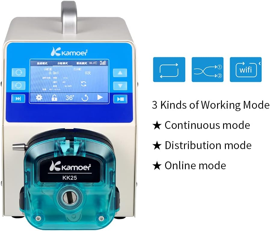
Figure 5.1: This image illustrates the pump's display interface, highlighting the three primary working modes: Continuous mode, Distribution mode, and Online mode. Icons representing each mode are also visible.
5.1 Continuous Mode
In Continuous mode, the pump operates at a constant speed, delivering fluid continuously until manually stopped. This mode is suitable for applications requiring a steady flow rate over an extended period.
5.2 Distribution Mode
Distribution mode allows for precise dispensing of specific volumes of liquid. Users can set parameters such as the volume per dose, the number of doses, and the interval between doses. This is ideal for repetitive batching or filling tasks.
5.3 Online Mode
Online mode enables external control of the pump, typically through the mobile application or other communication interfaces. This mode is used when the pump needs to be integrated into a larger automated system or controlled remotely within the LAN.
6. Control Methods
The Kamoer AIP pump offers multiple methods for control and operation, providing flexibility for various user preferences and system integrations.

Figure 6.1: The Kamoer AIP pump is shown in a laboratory setting connected with tubing and glassware. Text overlays describe the various control methods supported, such as thin film button, touch screen, external analog signal, dosing gun, and R485/CAN communication.
- Thin Film Button: Physical buttons on the front panel for basic operations.
- Touch Screen: The primary interface for setting parameters, selecting modes, and monitoring pump status.
- Mobile Phone APP (WiFi Control): Allows remote control and monitoring via a smartphone application when connected to the same 2.4G local area network.
- External Analog Signal Control: Supports 4-20mA and 0-5V analog inputs for integration with external control systems.
- Dosing Gun: Specific external device for triggering dosing operations.
- External R485/CAN Communication Control: For advanced integration into industrial control networks using RS485 or CAN protocols.
7. Specifications
Detailed technical specifications for the Kamoer AIP Peristaltic Pump.

Figure 7.1: This image features the pump alongside a list of its technical specifications, including motor type, voltage, power, flow range, memory function, delivery accuracy, maximum speed, working temperature, humidity, and physical dimensions.
| Feature | Specification |
|---|---|
| Brand | Kamoer |
| Model Number | AIP WIFI-S363-UK |
| Motor Type | Stepper Motor |
| Voltage | 100V-240V AC |
| Maximum Power | 150W |
| Flow Range | 1-6000 ml/min |
| Maximum Speed | 600 rpm |
| Delivery Accuracy | 0.1 RPM |
| Noise Level | <65dB |
| Motor Life | >6000 hours |
| Tube Size (ID x OD) | 9.6mm x 14.6mm (Silicone tube S36#) |
| Working Temperature | 0~50 °C |
| Relative Humidity | 10%-90% |
| Display | 4.3 inch Industrial Touch Screen |
| Control Methods | Thin film button, Touch screen, Mobile APP (WiFi), External analog signal (4-20mA, 0-5V), Dosing gun, External R485/CAN communication |
| Power Off Memory Function | Supported |
| Item Weight | 7.6 kg (15.4 lbs) |
| Dimensions (L*W*H) | 280*152*235 mm |
| Material | Stainless Steel |
8. Maintenance
8.1 Cleaning
- Regularly wipe the exterior of the pump with a soft, damp cloth. Avoid abrasive cleaners or solvents.
- Ensure no liquid enters the internal components of the pump.
- For the pump head, clean according to the type of fluid being transferred. Flush with appropriate cleaning solutions if necessary.
8.2 Tubing Replacement
- Peristaltic tubing is a wear-and-tear component. Replace tubing regularly based on usage and the type of fluid.
- Inspect tubing for signs of wear, cracks, or discoloration.
- To replace, open the pump head, remove the old tubing, and install new tubing as described in Section 4.2.
9. Troubleshooting
This section addresses common issues you might encounter with your Kamoer AIP pump.
| Problem | Possible Cause & Solution |
|---|---|
| Pump does not power on |
|
| No fluid flow or inconsistent flow |
|
| WiFi connection issues |
|
| Inaccurate dosing volume |
|
If you encounter issues not listed here or require further assistance, please contact Kamoer customer support.
10. Warranty and Support
Kamoer products are manufactured to high standards and come with a warranty against defects in materials and workmanship. Please refer to your purchase documentation for specific warranty terms and duration.
10.1 Certifications

Figure 10.1: This image displays various certifications for Kamoer products, including ISO, EC Declaration of Conformity, and RoHS, indicating compliance with international standards.
10.2 Customer Support
For technical support, warranty claims, or any inquiries regarding your Kamoer AIP Peristaltic Pump, please contact our customer service team.

Figure 10.2: This image provides contact details for Kamoer support, including an email address for inquiries.
Email: daijing@kamoer.com
Please provide your product model number (AIP WIFI-S363-UK) and purchase date when contacting support to expedite assistance.


