1. Introduction
This manual provides detailed instructions for the Stemedu HC-SR501 PIR Infrared Sensor and RCWL-0516 Microwave Radar Sensor modules. These modules are designed for detecting motion and are suitable for various applications including human body induction lighting and anti-theft alarms.
2. Product Overview
This package includes five (5) HC-SR501 PIR Motion Sensors and five (5) RCWL-0516 Microwave Radar Sensor Modules.

Image: Five HC-SR501 PIR Infrared Sensor modules, each featuring a white hemispherical lens on a green circuit board.

Image: Five RCWL-0516 Microwave Radar Sensor modules, each a rectangular green circuit board with an integrated circuit and pin headers.
3. Specifications
3.1. HC-SR501 PIR Motion Sensor
- Operating Voltage Range: DC 4.5V - 20V
- Quiescent Current: Less than 50µA
- Trigger Modes: L (Non-repeatable trigger) / H (Repeatable trigger) - Default is repeatable trigger.
- Delay Time: 5 - 200 seconds (adjustable, range from 0.xx seconds to tens of seconds)
3.2. RCWL-0516 Microwave Radar Sensor
- Operating Voltage Range: DC 4.0V - 28.0V
- Output Power Supply: 3.3V
- Detection Principle: Radar Doppler, microwave induction for moving objects.
- Features: High sensitivity, long induction distance, high reliability, wide induction angle, penetration detection capability (compared to traditional PIR sensors).
- Adjustments: Locking time and distance are adjustable.
4. Setup and Configuration
4.1. HC-SR501 PIR Motion Sensor Setup
The HC-SR501 module features two potentiometers for adjustment and a jumper for trigger mode selection.

Image: Close-up of an HC-SR501 module showing two orange potentiometers labeled 'Sensitivity' and 'Output timing'.
- Sensitivity Adjustment: Rotate the potentiometer to adjust the detection range.
- Delay Time Adjustment: Rotate the potentiometer to set the duration the output remains high after motion is detected.

Image: Diagrams illustrating clockwise/counter-clockwise rotation effects on delay and sensitivity, and jumper settings for trigger modes.
Delay Adjustment:
- Clockwise/Right: Increases delay (up to approximately 5 minutes).
- Counter-Clockwise/Left: Decreases delay (down to approximately 3 seconds).
Sensitivity Adjustment:
- Clockwise/Right: Decreases sensitivity, reducing the detection range (to approximately 3 meters).
- Counter-Clockwise/Left: Increases sensitivity, extending the detection range (to approximately 7 meters).
Trigger Mode Selection:
Use the jumper cap to select between Single Trigger Mode and Repeatable Trigger Mode.
- H (Repeatable Trigger): When motion is detected, the delay timer restarts with each new detection. The output remains high as long as motion is continuously detected within the delay period. This is the default setting.
- L (Single Trigger): When motion is detected, the delay timer starts. Subsequent motion detections during this delay period are ignored, and the output goes low after the set delay time expires.
4.2. RCWL-0516 Microwave Radar Sensor Setup
The RCWL-0516 module requires power input and provides a 3.3V output. It has specific pins for connection.

Image: RCWL-0516 module showing pin labels: DC OUT 3.3V, GND/0V, TTL OUT 3.3V (H), DC IN 4-28V, SENSOR DISABLE INPUT (L), and CDS (LDR) PADS.
- DC IN (4-28V): Connect your power supply within this voltage range.
- GND/0V: Ground connection.
- TTL OUT (3.3V H): Digital output pin. Goes high (3.3V) when motion is detected.
- DC OUT (3.3V): Provides a regulated 3.3V power supply for external components.
- SENSOR DISABLE INPUT (L): Can be used to disable the sensor.
- CDS (LDR) PADS: Pads for connecting a photoresistor (Light Dependent Resistor) to enable light-dependent operation.
For advanced users, a schematic diagram of the RCWL-0516 module is provided below:
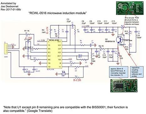
Image: Detailed circuit schematic for the RCWL-0516 microwave induction module, annotated with component values and functional blocks.
5. Operating Modes (HC-SR501)
The HC-SR501 sensor operates in two primary trigger modes, selectable via a jumper:
- Single Trigger Mode (L): Once motion is detected, the output goes high for the set delay time. Any further motion during this delay period is ignored. The output will only go high again after the current delay period has fully elapsed and new motion is detected.
- Repeatable Trigger Mode (H): This is the default mode. When motion is detected, the output goes high. If continuous motion is detected within the set delay time, the delay timer will reset with each new detection, keeping the output high. The output will only go low after no motion has been detected for the entire delay period.
6. Maintenance
These sensor modules are generally low-maintenance. To ensure optimal performance:
- Keep the sensor lenses (HC-SR501) and module surfaces clean and free from dust or obstructions.
- Avoid exposing the modules to extreme temperatures, humidity, or direct water contact.
- Ensure proper ventilation if enclosed in a casing to prevent overheating.
7. Troubleshooting
- Sensor not detecting motion:
- Verify power supply connections and voltage are within specified ranges.
- For HC-SR501, check sensitivity potentiometer setting. Adjust clockwise to increase range.
- Ensure there are no physical obstructions blocking the sensor's field of view.
- Test in different environments to rule out interference (e.g., strong air currents for PIR, large metal objects for Microwave).
- Sensor always triggered or false triggers:
- For HC-SR501, check sensitivity potentiometer setting. Adjust counter-clockwise to decrease range.
- Ensure the sensor is not placed near heat sources, air conditioning vents, or rapidly changing light conditions (for PIR).
- For RCWL-0516, ensure it's not detecting motion through thin walls or non-metallic objects if unintended.
- Check for loose connections or faulty wiring.
- Output signal not as expected:
- For HC-SR501, verify the delay time potentiometer setting.
- Check the trigger mode jumper setting (L or H) on the HC-SR501.
- Ensure the connected microcontroller or circuit is correctly interpreting the 3.3V TTL output.
8. Warranty and Support
For any issues, technical support, or warranty inquiries regarding your Stemedu sensor modules, please refer to the seller's contact information or the platform where the product was purchased. Please retain your proof of purchase for warranty claims.


