1. Introduction
The Midzoo FT232RL USB to Serial Adapter Module provides a reliable and efficient way to convert USB signals to serial (TTL) signals. This module is ideal for communicating with microcontrollers, such as Arduino Pro Mini, and other embedded systems that require a serial interface. It supports both 3.3V and 5.5V logic levels, making it versatile for various electronic projects.
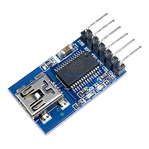
Figure 1: Top-down view of the Midzoo FT232RL USB to Serial Adapter Module, showing the mini USB port, the FT232RL chip, and the pin headers.
2. Key Features
- FT232RL Chip: Utilizes the genuine FT232RL chip for stable and reliable USB to serial conversion.
- Dual Voltage Support: Configurable for 3.3V or 5.5V (5V) operation, suitable for a wide range of microcontrollers.
- Mini USB Interface: Standard mini USB port for easy connection to a computer.
- Standard Pinout: Includes DTR, RXD, TXD, VCC, CTS, and GND pins for common serial communication.
- Compact Design: Small form factor, ideal for integration into projects with limited space.
3. Package Contents
Please verify that all items are present upon opening the package:
- 1 x Midzoo FT232RL USB to Serial Adapter Module
4. Setup Guide
4.1 Driver Installation
The FT232RL chip requires specific drivers to function correctly on your computer. These drivers are typically available from the FTDI website. Follow these steps:
- Download Drivers: Visit the official FTDI website (www.ftdichip.com/Drivers/VCP.htm) and download the appropriate VCP (Virtual COM Port) drivers for your operating system (Windows, macOS, Linux).
- Install Drivers: Follow the installation instructions provided by FTDI. For most operating systems, running the installer package will automatically install the necessary drivers.
- Connect Module: Connect the FT232RL module to your computer using a mini USB cable.
- Verify Installation: Open your computer's Device Manager (Windows) or check system information (macOS/Linux). Look for a new COM port (e.g., "USB Serial Port (COMx)") under "Ports (COM & LPT)" or similar. If the driver is installed correctly, the module will be recognized.
4.2 Voltage Selection
The module supports both 3.3V and 5.5V (5V) logic levels. The default voltage is typically 5V. To change the operating voltage, you may need to adjust a jumper or solder pad on the module. Refer to the image below for typical voltage selection points.
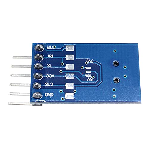
Figure 2: Bottom view of the module, highlighting solder pads for 3.3V and 5V selection. Ensure correct voltage is selected to match your target device.
- 5.5V (5V) Operation: Typically, the module is configured for 5V by default. This is suitable for most Arduino boards (e.g., Uno, Mega).
- 3.3V Operation: For devices requiring 3.3V logic (e.g., Arduino Pro Mini 3.3V, ESP32/ESP8266), you must ensure the module is set to 3.3V. This usually involves soldering a jumper or bridging specific pads on the underside of the board. Consult the specific markings on your module.
Warning: Connecting a 5V module to a 3.3V device can damage the 3.3V device. Always verify the voltage setting before connecting.
5. Operating Instructions
5.1 Pinout Description
The module features a 6-pin header for connecting to your target device. The standard pinout is as follows:
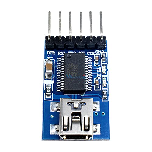
Figure 3: Close-up view of the 6-pin header on the FT232RL module, showing pin labels.
| Pin Label | Description |
|---|---|
| DTR | Data Terminal Ready. Often used for automatic reset of microcontrollers like Arduino. |
| RXD | Receive Data. Connect to the TXD (Transmit Data) pin of your target device. |
| TXD | Transmit Data. Connect to the RXD (Receive Data) pin of your target device. |
| VCC | Power Supply Output. Provides the selected voltage (3.3V or 5.5V) to the target device. |
| CTS | Clear To Send. Hardware flow control pin. Often not used for simple communication. |
| GND | Ground. Connect to the GND pin of your target device. |
5.2 Connecting to a Microcontroller (e.g., Arduino Pro Mini)
To program or communicate with a microcontroller using the FT232RL module, follow these general connection guidelines:
- Verify Voltage: Ensure the FT232RL module's VCC output matches the operating voltage of your microcontroller (e.g., 3.3V for Arduino Pro Mini 3.3V).
- Connect GND: Connect the GND pin of the FT232RL module to the GND pin of your microcontroller.
- Connect VCC: Connect the VCC pin of the FT232RL module to the VCC or RAW pin of your microcontroller (depending on the microcontroller's power input requirements).
- Connect TXD to RXD: Connect the TXD pin of the FT232RL module to the RXD pin of your microcontroller.
- Connect RXD to TXD: Connect the RXD pin of the FT232RL module to the TXD pin of your microcontroller.
- Connect DTR: Connect the DTR pin of the FT232RL module to the RST (Reset) pin of your microcontroller. This allows the programming software (e.g., Arduino IDE) to automatically reset the board for uploading code.
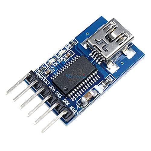
Figure 4: Angled view of the module, illustrating typical connection points for serial communication.
6. Maintenance
- Storage: Store the module in a dry, anti-static environment when not in use.
- Cleaning: If necessary, gently clean the module with a soft, dry cloth. Avoid using liquids or harsh chemicals.
- Handling: Handle the module by its edges to avoid touching the electronic components, which can be sensitive to static discharge.
7. Troubleshooting
| Problem | Possible Cause | Solution |
|---|---|---|
| Module not recognized by computer. | Drivers not installed or incorrectly installed. Faulty USB cable. | Ensure FTDI VCP drivers are correctly installed. Try a different mini USB cable. Test on another USB port or computer. |
| Communication errors (e.g., garbled text, failed uploads). | Incorrect TXD/RXD connection. Mismatched baud rates. Incorrect voltage level. | Double-check TXD-to-RXD and RXD-to-TXD connections. Verify baud rates match on both ends. Confirm module voltage matches target device voltage. |
| Target device not powering on or behaving erratically. | Incorrect VCC connection or voltage selection. Insufficient current from USB port. | Ensure VCC is connected correctly and the module's voltage output matches the device. If powering a high-current device, use an external power supply for the device. |
8. Specifications
| Feature | Detail |
|---|---|
| Chipset | FT232RL |
| Interface | Mini USB to TTL Serial (6-pin header) |
| Logic Voltage | Selectable 3.3V or 5.5V (5V) |
| USB Connector | Mini USB Type-B |
| Pinout | DTR, RXD, TXD, VCC, CTS, GND |
| Compatibility | Windows, macOS, Linux (with FTDI VCP drivers) |
9. Safety Information
- Always ensure the correct voltage is selected for your target device to prevent damage.
- Avoid short circuits between pins.
- Do not expose the module to moisture or extreme temperatures.
- This product is intended for educational and hobbyist use. Professional applications may require additional safety considerations.
10. Warranty and Support
For technical support or warranty inquiries, please contact your retailer or the manufacturer, Midzoo. Please have your product model number (FT232RL) and purchase information available when contacting support.


