1. Introduction
This manual provides detailed instructions for the installation, operation, and maintenance of your Xigmatek Aero Black Micro-ATX Case. Please read this manual thoroughly before beginning assembly to ensure proper setup and to maximize the lifespan of your components.
2. Product Overview
The Xigmatek Aero is a compact Micro-ATX PC case designed for efficient component housing and airflow. It features a simple and stylish design, incorporating a tempered glass front panel and an acrylic side panel for visibility of internal components.
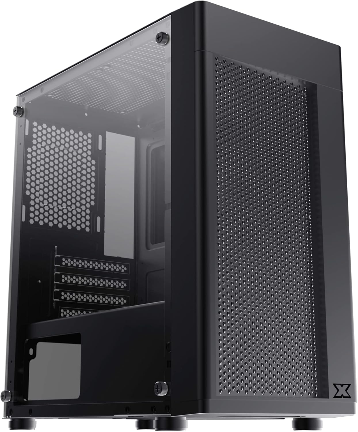
Figure 2.1: Front-left view of the Xigmatek Aero Black Micro-ATX Case, showcasing the tempered glass front panel and acrylic side panel.
3. Key Features
- Tempered Glass Side Panel: Provides a clear view of internal components.
- Bottom Mounted PSU: Dedicated compartment for power supply unit, aiding in thermal management and cable routing.
- Mesh Design Front Panel: Enhances airflow for improved cooling performance.
- Easy Cable Management: Designed with routing options and a PSU shroud to facilitate neat cable organization.
- Compact Micro-ATX Form Factor: Optimized for smaller builds while maintaining compatibility with standard components.
4. Package Contents
Please verify that all items are present in the package before proceeding with installation:
- Xigmatek Aero Black Micro-ATX Case
- Accessory Box (containing screws, standoffs, zip ties)
- User Manual (this document)
5. Setup and Installation
Follow these steps carefully for proper installation of your PC components into the Xigmatek Aero case.
5.1 Preparing the Case
- Place the case on a flat, stable surface.
- Carefully remove the tempered glass side panel by unscrewing the four thumb screws. Set the panel aside on a soft, non-abrasive surface to prevent scratches.
- Remove the rear side panel (solid metal panel) by unscrewing the two thumb screws at the back and sliding it off. This provides access for cable management.
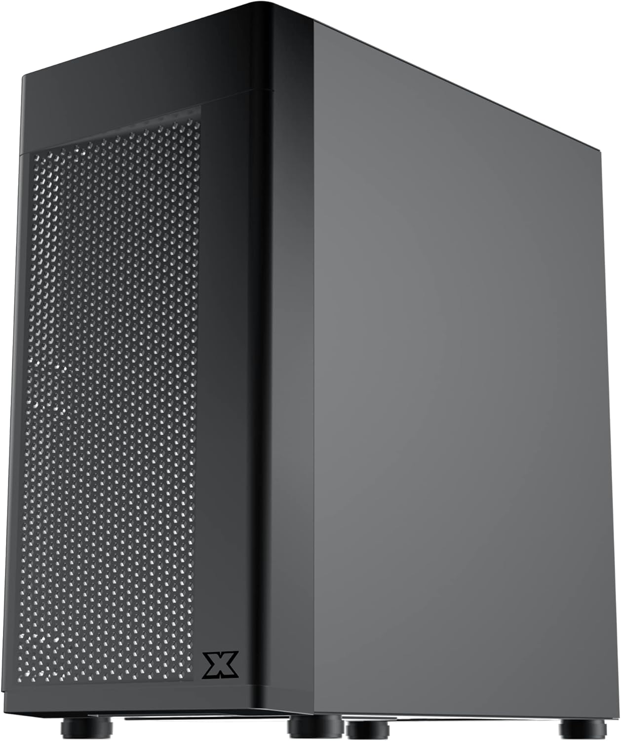
Figure 5.1: Side view of the case, showing the tempered glass panel secured by four thumb screws.
5.2 Power Supply Unit (PSU) Installation
- Locate the PSU mounting area at the bottom rear of the case, within the PSU shroud.
- Slide your PSU into the designated slot from the rear of the case. Ensure the PSU fan faces downwards (if the case has a bottom vent) or upwards, depending on your cooling preference and PSU design.
- Secure the PSU with screws from the rear of the case.
- Route necessary PSU cables through the cutouts in the PSU shroud to the main compartment.

Figure 5.2: Internal view highlighting the PSU shroud and cable routing options.
5.3 Motherboard Installation
- Install the I/O shield (if applicable) into the rear opening of the case.
- Align your Micro-ATX motherboard with the pre-installed standoffs. Ensure the screw holes on the motherboard match the standoffs.
- Secure the motherboard using the provided screws. Do not overtighten.

Figure 5.3: Internal view of the case, showing the motherboard tray and standoff locations.
5.4 Storage Drive Installation
The case supports 3.5-inch HDDs and 2.5-inch SSDs.
- 3.5" HDD: Locate the drive cage under the PSU shroud. Slide the HDD into the drive bay and secure with screws. Note: Some users find it easier to remove the drive caddy by unscrewing from the underside of the case first.
- 2.5" SSD: SSDs can typically be mounted on dedicated brackets behind the motherboard tray or on top of the PSU shroud. Secure with screws.
5.5 Graphics Card and Expansion Cards
- Remove the necessary expansion slot covers from the rear of the case. These are break-off covers, so bend them carefully until they detach.
- Insert your graphics card or other expansion cards into the appropriate PCIe slots on your motherboard.
- Secure the cards with screws.

Figure 5.4: Rear view of the case, showing expansion slots and I/O shield opening.
5.6 Fan and Cooling Installation
The Xigmatek Aero supports multiple fan configurations for optimal airflow.
- Front: Up to 2x 120mm or 140mm fans. Can also support a 240mm AIO liquid cooler.
- Top: Up to 2x 120mm fans.
- Rear: 1x 120mm fan.
Install fans by aligning them with the screw holes and securing them with fan screws. Pay attention to airflow direction (intake vs. exhaust).
5.7 Cable Management
Utilize the cutouts and tie-down points behind the motherboard tray to route and secure cables. This improves airflow and aesthetics.

Figure 5.5: View from the rear of the motherboard tray, showing space for cable routing.
5.8 Front Panel Connections
Connect the front panel cables (USB 3.0, USB 2.0, Audio, Power LED, HDD LED, Power Switch, Reset Switch) to the corresponding headers on your motherboard. Refer to your motherboard manual for exact pin layouts.

Figure 5.6: Top view of the case, illustrating the front I/O ports including USB 3.0 and audio jacks.
5.9 Final Assembly
- Once all components are installed and cables are managed, reattach the rear side panel.
- Carefully reattach the tempered glass side panel and secure it with the four thumb screws.
6. Operating Considerations
To ensure optimal performance and longevity of your system:
- Airflow: Ensure proper fan configuration for intake and exhaust to maintain good internal temperatures. The mesh front panel is designed for excellent air intake.
- Placement: Place the PC case on a hard, flat surface to allow adequate airflow to the bottom-mounted PSU and any bottom intake fans. Avoid placing it on carpet.
7. Maintenance
Regular maintenance helps preserve your system's performance and extends its lifespan:
- Dust Cleaning: Periodically clean dust from the case interior and fan filters. The top panel features a magnetic dust filter for easy removal and cleaning.
- Exterior Cleaning: Use a soft, damp cloth to clean the exterior surfaces. Avoid abrasive cleaners. For the tempered glass and acrylic panels, use a microfiber cloth and a gentle glass cleaner.
8. Troubleshooting
If you encounter issues during or after assembly, consider the following:
- System Not Powering On:
- Ensure all PSU cables are securely connected to the motherboard and components.
- Verify the front panel power switch cable is correctly connected to the motherboard header.
- Check the PSU switch is in the 'ON' position.
- Fans Not Spinning:
- Confirm fan cables are properly connected to motherboard fan headers or a fan controller.
- Poor Airflow/High Temperatures:
- Check fan orientation (intake/exhaust).
- Ensure dust filters are clean.
- Verify no cables are obstructing airflow.
9. Specifications
| Feature | Detail |
|---|---|
| Model Number | EN46584 |
| Form Factor | Micro-ATX Tower |
| Dimensions (L x W x H) | 34.5 x 20 x 29 cm |
| Weight | 3.53 kg |
| Material | Tempered Glass, Acrylic, Steel |
| Motherboard Compatibility | Micro ATX, Mini-ITX |
| PSU Mounting | Bottom Mount |
| Drive Bays | 1x 3.5" HDD, 2x 2.5" SSD (or 2x 3.5" HDD, 1x 2.5" SSD depending on configuration) |
| Expansion Slots | 4 |
| Fan Support (Front) | 2x 120mm / 140mm |
| Fan Support (Top) | 2x 120mm |
| Fan Support (Rear) | 1x 120mm |
| Radiator Support (Front) | Up to 240mm |
| Front I/O Ports | 1x USB 3.0, 2x USB 2.0, HD Audio (Mic & Headphone) |
10. Warranty and Support
For warranty information and technical support, please refer to the official Xigmatek website or contact your local retailer. Keep your proof of purchase for warranty claims.


