
1. Introduction
Thank you for choosing the Xprite Alert 6 Series White Amber LED Emergency Strobe Lights Kit. This manual provides essential information for the proper installation, operation, and maintenance of your new strobe lights. Please read this manual thoroughly before installation and retain it for future reference.
The Xprite Alert 6 Series features an ultra-thin, flush-mount design with super bright, high-intensity LED chips, offering enhanced visibility and performance for various vehicles.
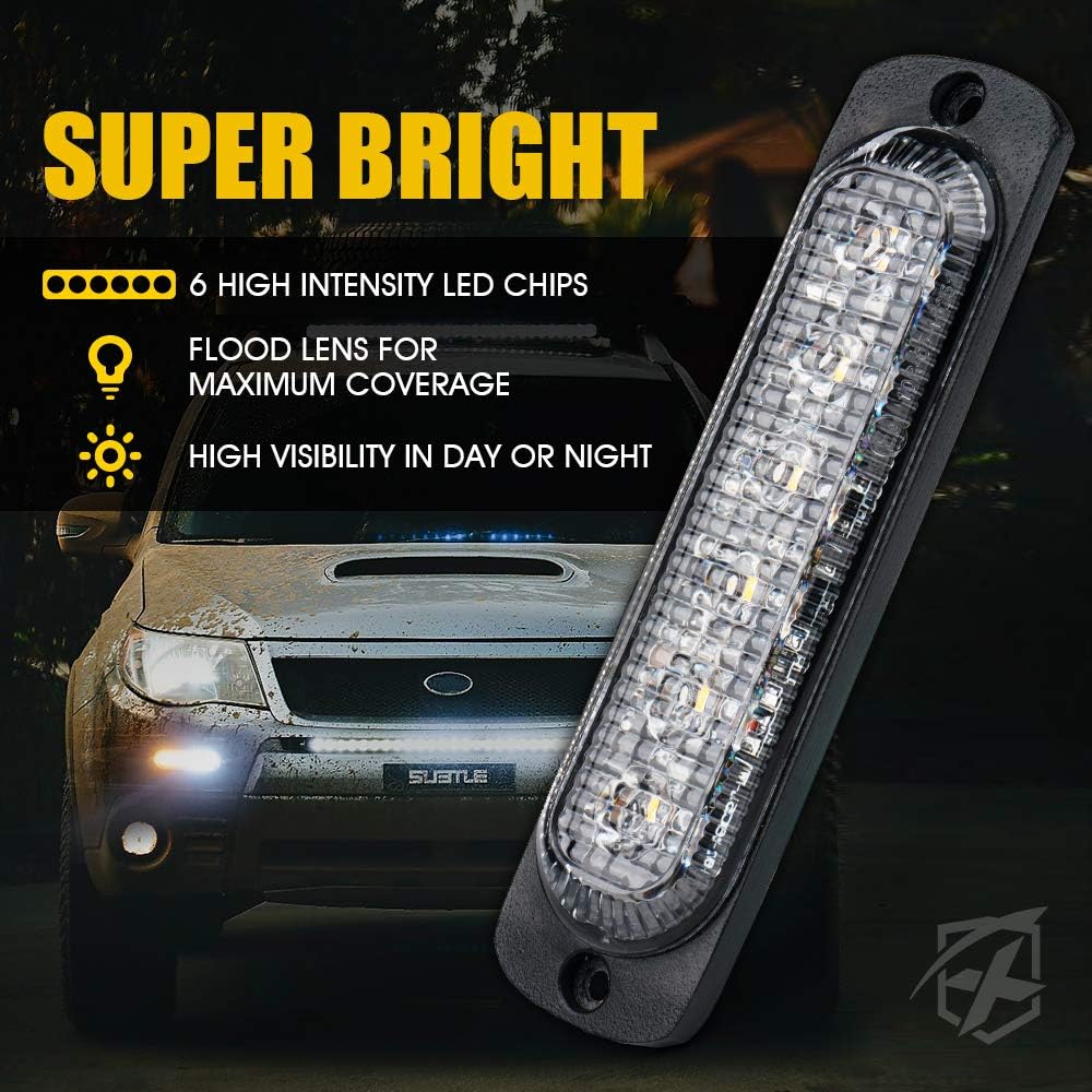
Image 1.1: The Xprite Alert 6 Series LED Strobe Light, emphasizing its super bright output from 6 high-intensity LED chips and flood lens for maximum coverage, ensuring high visibility day or night.
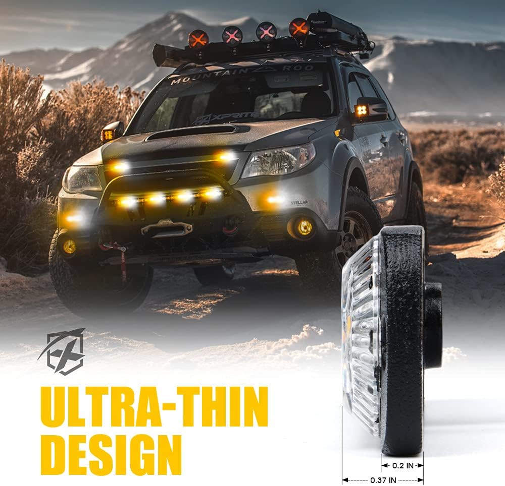
Image 1.2: A side profile view of the Xprite Alert 6 Series LED Strobe Light, illustrating its ultra-thin design with a thickness of approximately 0.37 inches.
2. Package Contents
Please check the package contents upon receipt to ensure all items are present and undamaged:
- 8 x Xprite Alert 6 Series LED Strobe Light Modules
- 8 x Mounting Gaskets
- Mounting Screws (quantity sufficient for all modules)
3. Safety Information
To ensure safe operation and prevent damage, please observe the following safety guidelines:
- Power Source: This product is designed for 12V DC vehicle power systems. Do not connect to higher voltage systems.
- Professional Installation: If you are unsure about electrical wiring, it is recommended to have the lights installed by a qualified professional.
- Wiring: Ensure all wiring is properly insulated and secured to prevent short circuits and damage.
- Mounting: Mount the lights securely to prevent them from detaching during vehicle operation.
- Local Regulations: Always check local and provincial/state laws regarding the use of emergency and warning lights on vehicles.
- Heat: While LEDs produce less heat than traditional bulbs, ensure adequate ventilation around the lights.
4. Setup and Installation
Follow these steps for proper installation of your Xprite Alert 6 Series LED Strobe Lights:
- Choose Mounting Location: Select a flat, secure surface on your vehicle for flush mounting. Ensure there is enough space behind the mounting surface for wiring.
- Prepare Surface: Clean the mounting surface thoroughly to remove any dirt, grease, or debris.
- Drill Holes: Mark the positions for the mounting screws and the wiring pass-through. Carefully drill pilot holes for the screws and a larger hole for the wires.
- Wiring Connection: Connect the wires according to the diagram below. Ensure all connections are secure and insulated.
- Red Wire: Connect to Positive (+) 12V DC power source.
- Black Wire: Connect to Ground (-).
- Yellow Wire: Momentarily touch to Positive (+) to change flashing patterns.
- White Wire: Connect to the white wire of other light modules for Synchronization.
- Gray Wire: Connect to Positive (+) for Static/Steady On mode.
- Mount Lights: Place the gasket between the light module and the mounting surface. Secure the light module using the provided screws. Do not overtighten.
- Test Functionality: After installation, test all lights and patterns to ensure proper operation.
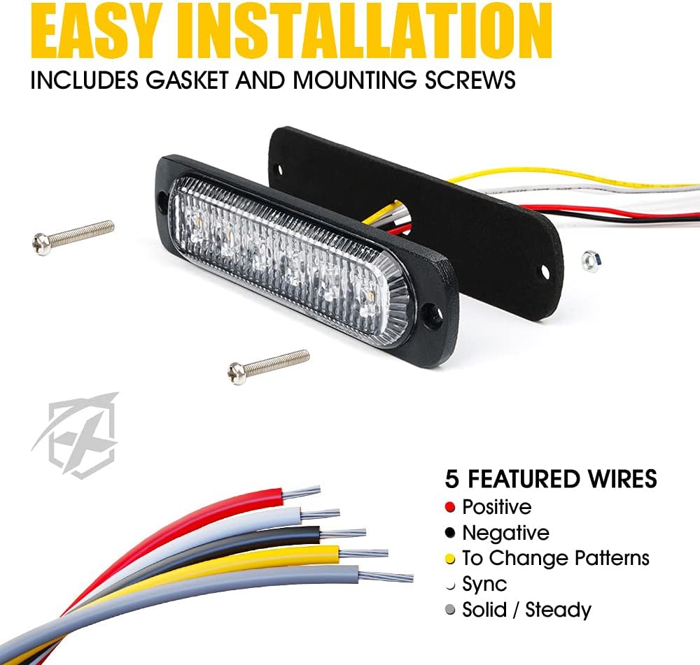
Image 4.1: Diagram illustrating the easy installation process, including the light module, gasket, mounting screws, and the five featured wires with their respective functions (Positive, Negative, Change Patterns, Sync, Solid/Steady).
5. Operating Instructions
Your Xprite Alert 6 Series LED Strobe Lights offer multiple flashing patterns and synchronization capabilities.
5.1 Changing Flashing Patterns
To cycle through the 18 available flashing patterns, momentarily touch the Yellow Wire to the Positive (+) power source. Each brief touch will advance to the next pattern. The lights feature a last pattern memory recall function, meaning they will power on to the last selected pattern.
5.2 Synchronization Function
To synchronize multiple light modules, connect the White Wire of each light module together. Ensure all white wires are connected before applying positive and negative power to the lights. This will allow all connected lights to flash in unison.
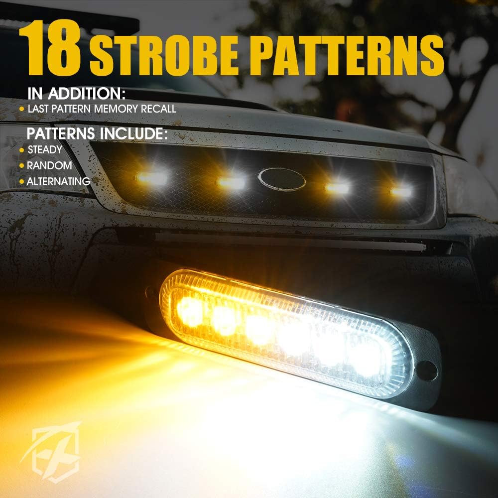
Image 5.1: Visual representation of the 18 strobe patterns available, including steady, random, and alternating modes, along with the last pattern memory recall feature.
6. Maintenance
The Xprite Alert 6 Series LED Strobe Lights are designed for durability and minimal maintenance. They are waterproof, shock, and vibration resistant, built to withstand harsh weather conditions.
- Cleaning: Periodically clean the lens with a soft cloth and mild soap and water to maintain optimal light output. Avoid abrasive cleaners.
- Inspection: Regularly inspect wiring and connections for any signs of wear, corrosion, or damage. Ensure mounting screws remain tight.
- No User-Serviceable Parts: Do not attempt to open or repair the light modules, as this will void any potential warranty and may damage the unit.

Image 6.1: Illustration highlighting the waterproof, shock, and vibration resistant features of the Xprite Alert 6 Series LED Strobe Light, designed for durability in harsh conditions.
7. Troubleshooting
If you encounter issues with your strobe lights, refer to the following troubleshooting guide:
| Problem | Possible Cause | Solution |
|---|---|---|
| Lights do not turn on | No power, poor ground connection, faulty wiring, blown fuse | Check power supply, ground connection, all wiring, and vehicle fuse. Ensure correct voltage (12V). |
| Lights not syncing | White wires not connected, poor connection on white wires | Ensure all white wires are securely connected together. Verify connections are made before applying main power. |
| Cannot change patterns | Yellow wire not making contact with positive, faulty yellow wire | Ensure the yellow wire is momentarily touched to a positive 12V source. Check the integrity of the yellow wire. |
| One light not working | Faulty unit, wiring issue to that specific light | Check power and ground connections to the individual light. If wiring is correct, the unit may be faulty. |
8. Specifications
| Feature | Specification |
|---|---|
| Model Number | 52026T-6-WY-8PC |
| Light Source | LED |
| Number of LEDs per Module | 6 High-Intensity LED Chips |
| Input Voltage | 10-30V DC (Nominal 12V) |
| Wattage | 4.8 Watts per module |
| Strobe Patterns | 18 (including steady, random, alternating) |
| Special Features | Waterproof, Shock & Vibration Resistant, Last Pattern Memory Recall |
| Rated Lifetime | Over 50,000 Hours |
| Cable Length | 8.2 FT (approx. 2.5 meters) |
| Dimensions (approx.) | 3.99 in (L) x 1.11 in (W) x 0.37 in (H) |
| Operating Temperature | Not specified (designed for harsh conditions) |
| UPC | 760249910972 |

Image 8.1: Diagram detailing key product specifications including dimensions (3.99 in length, 1.11 in width), number of LEDs, voltage, strobe patterns, and cable length.
9. Warranty and Support
For warranty information and customer support, please refer to the retailer's return policy or contact Xprite directly through their official website or the platform where the product was purchased. Please have your model number (52026T-6-WY-8PC) and proof of purchase ready when contacting support.
For more products and information, visit the Xprite Store.