1. Introduction
The Neoteck XL830L is a compact, manual-ranging digital multimeter designed for measuring DC/AC voltage, DC current, resistance, diode, continuity, and transistor hFE. It features a large, backlit LCD display for clear readings in various lighting conditions and includes overload protection for safe operation. This manual provides essential information for the safe and effective use of your multimeter.
2. Safety Information
Always adhere to safety precautions when using any electrical testing equipment. Failure to do so may result in electric shock, injury, or damage to the meter or the equipment under test.
- This meter is designed to meet CAT II 600V safety standards.
- Do not apply voltage or current that exceeds the maximum specified limits for the meter.
- Ensure the test leads are properly connected and the function switch is set to the correct range before making any measurements.
- Never measure resistance, continuity, or diode on a live circuit.
- Exercise extreme caution when working with voltages above 30V AC RMS, 42V peak, or 60V DC. These voltages pose a shock hazard.
- Replace the battery when the low battery indicator appears to ensure accurate readings.
- Do not operate the meter if it appears damaged or if the test leads are damaged.
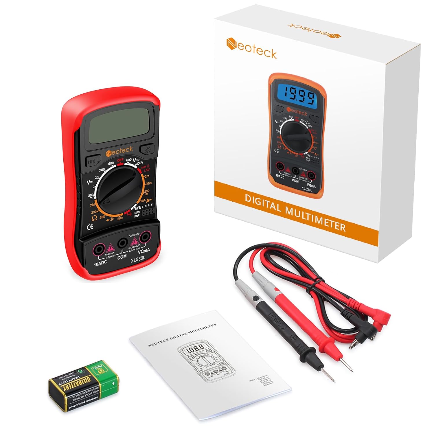
3. Package Contents
Verify that all items are present in the package:
- Neoteck Digital Multimeter XL830L
- Test Leads (Red and Black)
- 9V Battery
- User Manual
4. Product Features
- Measures DC/AC Voltage, DC Current, Resistance.
- Manual Ranging for precise control.
- Diode and Continuity Test functions.
- Transistor hFE (NPN/PNP) test.
- Large LCD with backlight for visibility in low-light conditions.
- Automatic polarity indication.
- Low battery indication.
- Overload protection (CAT II 600V rated).
- Durable orange protective rubber case with an integrated 45° kickstand.
5. Component Identification
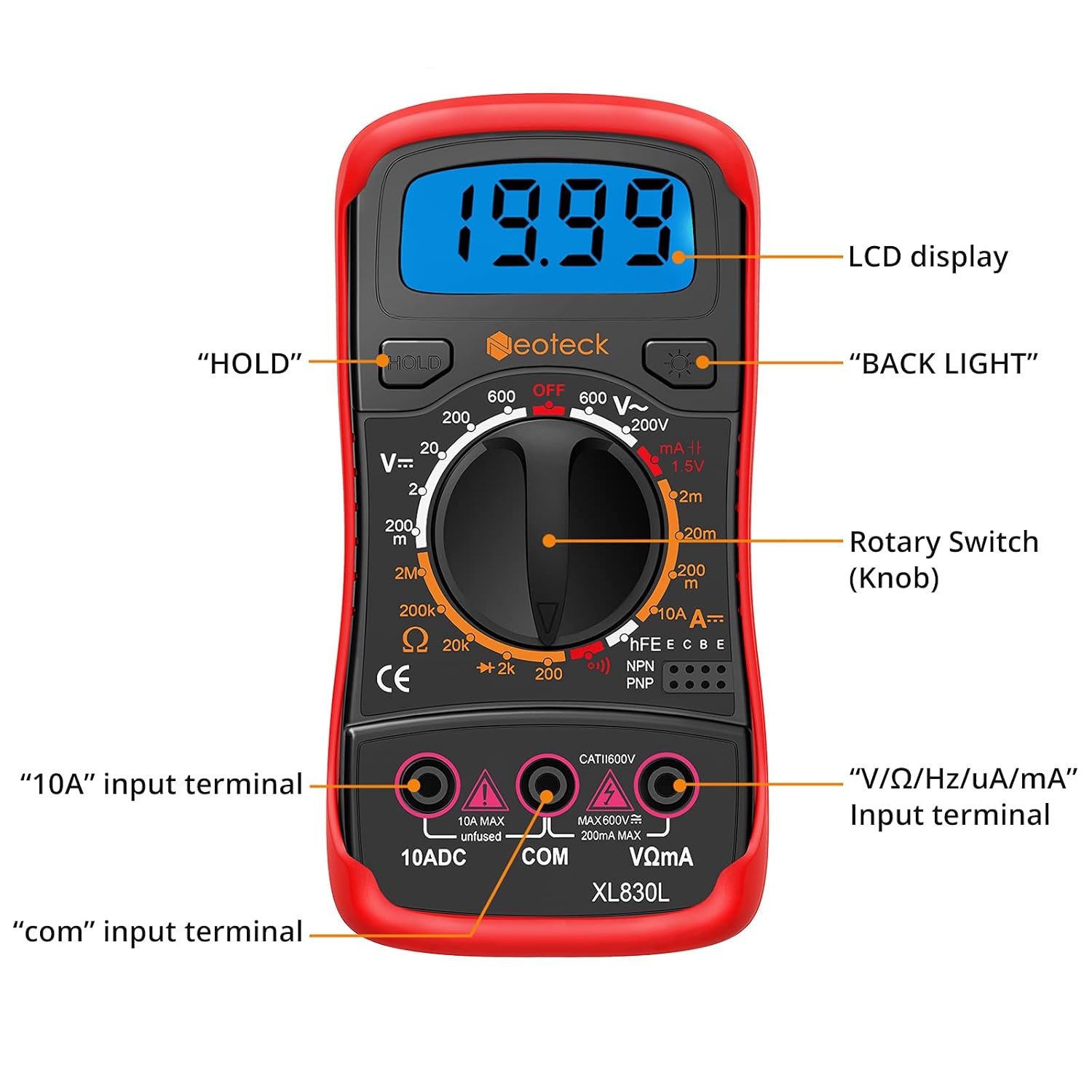
- LCD Display: Shows measurement readings, units, and indicators.
- HOLD Button: Freezes the current display reading.
- BACK LIGHT Button: Activates the display backlight for better visibility.
- Rotary Switch (Knob): Selects the desired measurement function and range.
- "10A" Input Terminal: For measuring DC current up to 10 Amperes.
- "COM" Input Terminal: Common (negative) terminal for all measurements.
- "V/Ω/Hz/uA/mA" Input Terminal: For measuring voltage, resistance, frequency, and current up to 200mA.


6. Setup
6.1. Battery Installation
- Ensure the multimeter is turned OFF.
- Locate the battery compartment cover on the back of the meter.
- Remove the screw(s) securing the cover and open it.
- Connect the 9V battery to the battery clips, observing correct polarity (+ and -).
- Place the battery into the compartment and replace the cover, securing it with the screw(s).
6.2. Connecting Test Leads
Always connect the black test lead to the "COM" (common) terminal. Connect the red test lead to the appropriate input terminal based on the measurement type:
- For Voltage (V), Resistance (Ω), Diode, Continuity, and small Current (uA/mA) measurements, connect the red lead to the V/Ω/Hz/uA/mA terminal.
- For large DC Current (up to 10A) measurements, connect the red lead to the 10ADC terminal.
7. Operating Instructions
To begin a measurement, turn the rotary switch from the "OFF" position to the desired function and range. Connect the test leads as described in Section 6.2.
7.1. DC Voltage Measurement (V=)
- Set the rotary switch to the desired DC Voltage range (e.g., 20V, 200V, 600V).
- Connect the red test lead to the V/Ω/Hz/uA/mA terminal and the black test lead to the COM terminal.
- Touch the red probe to the positive side of the circuit and the black probe to the negative side.
- Read the voltage value on the LCD.
7.2. AC Voltage Measurement (V~)
- Set the rotary switch to the desired AC Voltage range (e.g., 200V, 600V).
- Connect the red test lead to the V/Ω/Hz/uA/mA terminal and the black test lead to the COM terminal.
- Touch the probes to the AC voltage source.
- Read the voltage value on the LCD.
7.3. DC Current Measurement (A=)
CAUTION: Never connect the meter in parallel with a voltage source when measuring current. This can blow the fuse or damage the meter.
- Determine the expected current. For currents up to 200mA, use the uA/mA ranges. For currents up to 10A, use the 10ADC range.
- Set the rotary switch to the appropriate DC Current range.
- Connect the red test lead to the V/Ω/Hz/uA/mA terminal (for uA/mA) or the 10ADC terminal (for 10A). Connect the black test lead to the COM terminal.
- Open the circuit where current is to be measured and connect the meter in series with the load.
- Read the current value on the LCD.
7.4. Resistance Measurement (Ω)
CAUTION: Ensure the circuit is de-energized and all capacitors are discharged before measuring resistance.
- Set the rotary switch to the desired Resistance range (e.g., 200Ω, 2kΩ, 20kΩ, 200kΩ, 2MΩ).
- Connect the red test lead to the V/Ω/Hz/uA/mA terminal and the black test lead to the COM terminal.
- Touch the probes across the component or circuit segment to be measured.
- Read the resistance value on the LCD.
7.5. Diode Test (→|)
- Set the rotary switch to the Diode Test position.
- Connect the red test lead to the V/Ω/Hz/uA/mA terminal and the black test lead to the COM terminal.
- Touch the red probe to the anode of the diode and the black probe to the cathode. The display will show the forward voltage drop.
- Reverse the probes. The display should show "OL" (Open Loop) for a good diode.
7.6. Continuity Test ())))
- Set the rotary switch to the Continuity Test position.
- Connect the red test lead to the V/Ω/Hz/uA/mA terminal and the black test lead to the COM terminal.
- Touch the probes across the circuit or component. If resistance is below approximately 50Ω, the buzzer will sound, indicating continuity.

7.7. Transistor hFE Test (hFE)
- Set the rotary switch to the hFE position.
- Identify if the transistor is NPN or PNP.
- Insert the transistor's emitter, base, and collector leads into the corresponding holes in the hFE socket on the meter.
- Read the hFE (DC current gain) value on the LCD.
7.8. Backlight Function
Press the "BACK LIGHT" button to turn the display backlight on or off. This improves visibility in dimly lit environments.
7.9. Data Hold Function
Press the "HOLD" button to freeze the current reading on the display. Press it again to release the hold and resume live measurements.
8. Maintenance
8.1. Battery Replacement
When the low battery indicator appears on the LCD, replace the 9V battery immediately to ensure accurate measurements. Follow the steps in Section 6.1 for battery installation.
8.2. Cleaning
Wipe the meter's case with a damp cloth and a mild detergent. Do not use abrasives or solvents. Keep the terminals free from dirt and moisture.
8.3. Storage
If the meter is not used for an extended period, remove the battery to prevent leakage and damage. Store the meter in a cool, dry place away from direct sunlight.
9. Troubleshooting
- No display or faint display: Check the 9V battery. Replace if necessary.
- Incorrect readings:
- Ensure the rotary switch is set to the correct function and range.
- Verify test lead connections are secure and in the correct terminals.
- Check if the battery is low.
- Ensure the circuit under test is de-energized for resistance, diode, and continuity measurements.
- "OL" (Overload) displayed: The measured value exceeds the selected range. Switch to a higher range or check if the circuit is open (for continuity/resistance).
- No continuity buzzer: Check if the resistance is above the threshold (approx. 50Ω).
10. Specifications
| Parameter | Value |
|---|---|
| Model Number | NTK128 (XL830L) |
| Display | LCD with Backlight, 2000 Counts |
| Power Source | 1 x 9V Battery (included) |
| DC Voltage Range | 200mV / 2V / 20V / 200V / 600V |
| AC Voltage Range | 200V / 600V |
| DC Current Range | 200uA / 2mA / 20mA / 200mA / 10A |
| Resistance Range | 200Ω / 2kΩ / 20kΩ / 200kΩ / 2MΩ |
| Diode Test | Yes |
| Continuity Test | Yes (with Buzzer) |
| Transistor hFE Test | Yes (NPN/PNP) |
| Safety Rating | CAT II 600V |
| Operating Temperature | 0°C to 40°C (32°F to 104°F) |
| Dimensions | 15.7 x 10.39 x 4.9 cm |
| Weight | 281 grams |
11. Warranty and Support
For warranty information or technical support, please refer to the contact details provided with your purchase or visit the official Neoteck website. Keep your purchase receipt as proof of purchase.


