1. Introduction
This manual provides comprehensive instructions for the Radiolink R7FG 7-Channel Gyro Receiver. The R7FG is a 2.4GHz receiver designed for RC cars and boats, offering integrated telemetry, a built-in gyroscope, and water splash protection. It is compatible with various Radiolink transmitters, including the RC6GS V3/V2/RC6GS, RC4GS V3/V2/RC4GS, RC8X, T8S, and T8FB.

Image 1.1: Two Radiolink R7FG 7-Channel Gyro Receivers.
2. Key Features
- FHSS Spread Spectrum Technology: Utilizes 67-channel pseudo-random frequency hopping for superb anti-interference ability, allowing multiple users simultaneously.
- Integrated Gyroscope: Enhances stability and control for various RC vehicles.
- Telemetry Capabilities: Provides real-time data for model voltage, receiver voltage, and RSSI (Received Signal Strength Indication).
- Water Splash Proof (IPX4): Designed to withstand water splashes, suitable for diverse environments.
- Anti-Reverse Polarity Protection: Protects the receiver from damage due to incorrect power connection.
- Long Control Range: Offers a control range of up to 600 meters (1969 feet) on the ground.
- Low Latency Response: Ensures quick and precise control across all 7 channels.
- Easy One-Time Binding: Each receiver has a specific ID, requiring only a single binding process.
- Voltage Range: Operates within 3V to 12V DC.
- Signal Output: Supports SBUS/PPM/PWM signal output.
Image 2.1: Overview of Radiolink R7FG Key Features.
3. Specifications
| Feature | Specification |
|---|---|
| Model Number | R7FG V2 |
| Channels | 7 Channels |
| Frequency | 2.4GHz FHSS |
| Operating Voltage | 3.0V - 12V DC |
| Signal Output | SBUS/PPM/PWM |
| Control Range | Up to 600 meters (1969 feet) on ground |
| Dimensions | 1.37 x 0.86 x 0.5 inches (35 x 22 x 13 mm) |
| Item Weight | 1.44 ounces (6g) |
| Water Resistance | IPX4 Water Splash Proof |

Image 3.1: R7FG Receiver Dimensions and Compatible Transmitters.
4. Compatibility
The R7FG receiver is compatible with the following Radiolink transmitters:
- Radiolink RC6GS V3
- Radiolink RC6GS V2
- Radiolink RC6GS
- Radiolink RC4GS V3
- Radiolink RC4GS V2
- Radiolink RC4GS
- Radiolink RC8X
- Radiolink T8S
- Radiolink T8FB
It is suitable for a wide range of RC vehicles, including:
- RC Crawlers
- Trucks
- Buggies
- Tanks
- Drifting Cars
- Gasoline Cars
- RC Boats

Image 4.1: Examples of Compatible RC Vehicles.
5. Setup
5.1 Wiring Diagram
Proper connection of the R7FG receiver is crucial for optimal performance. The receiver supports telemetry for vehicle voltage up to 8S (33.6V). Connect the telemetry cable to the designated telemetry port on the receiver and to your Electronic Speed Control (ESC) or battery as shown in the diagram below.
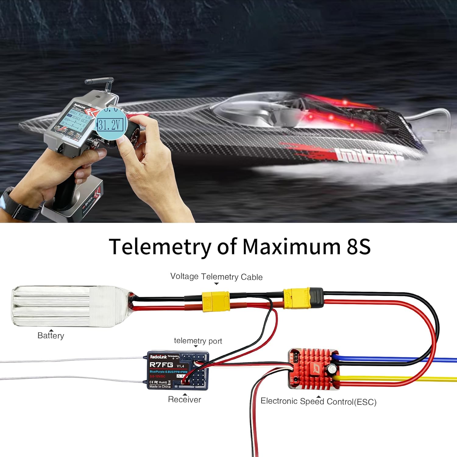
Image 5.1: Telemetry Wiring Diagram for R7FG Receiver.
5.2 Receiver Pinout
The R7FG receiver features multiple channels and ports for various connections:
- CH1 (Steering)
- CH2 (Throttle)
- CH3 (Auxiliary)
- CH4 (Auxiliary)
- CH5 (Auxiliary)
- CH6 (PPM Signal)
- CH7 (SBUS Signal)
- Telemetry Port (2Pin)
- VCC/GND

Image 5.2: R7FG Receiver Pinout and Connections.
5.3 Binding Process
The R7FG receiver features an easy one-time binding process. Each receiver has a unique ID, so it only needs to be bound once to your transmitter. The transmitter will remember the receiver for future use.
- Ensure both the transmitter and receiver are powered off.
- Press and hold the bind button on the R7FG receiver.
- While holding the bind button, power on the receiver. The LED on the receiver will flash rapidly.
- Release the bind button.
- Power on your Radiolink transmitter.
- The LED on the receiver should turn solid green, indicating successful binding. A signal tower icon will appear on the transmitter screen.

Image 5.3: Binding Button and LED Indicators.
6. Operating Instructions
6.1 Gyro Mode Switching
The R7FG receiver has a built-in gyroscope that can be switched between normal mode and gyro mode. This feature helps stabilize your RC vehicle, especially in challenging conditions.
- To switch to gyro mode: Quickly press the bind button 3 times within 1 second. The LED on the receiver will change from green (Normal Mode) to red (Gyro Mode).
- To switch back to normal mode: Repeat the process (press the bind button 3 times within 1 second). The LED will change from red to green.

Image 6.1: Gyro Functionality for RC Vehicles.
6.2 Telemetry Function
The R7FG receiver provides real-time telemetry data to your compatible Radiolink transmitter. This includes the vehicle's main battery voltage, receiver voltage, and Received Signal Strength Indication (RSSI).
To view telemetry data, ensure your transmitter is properly configured to display these values. The vehicle's voltage can be monitored up to 8S (33.6V).

Image 6.2: Telemetry Displaying Vehicle Voltage.
Video 6.1: Demonstrates real-time vehicle voltage telemetry using an RC6GS V3 transmitter and R7FG receiver. This video shows how the transmitter displays the vehicle's battery voltage, providing crucial information during operation.
Video 6.2: Illustrates how the R7FG receiver supports telemetry for vehicle voltage and provides low voltage alarms. This video highlights the safety feature that alerts users when the vehicle's battery is running low.
6.3 ID SEED Function
The ID SEED function allows you to switch control between multiple RC models using a single transmitter without re-binding. This is particularly useful for users with several vehicles.
- Turn on the ID SEED function in your transmitter's menu. Note that binding records will be cleared.
- Select the corresponding seed ID (e.g., ID01) for your first vehicle and perform the binding process.
- Repeat for other vehicles, assigning a unique ID (e.g., ID02) to each.
- Once set up, you can switch between models on the running by selecting their respective IDs on the transmitter.
Video 6.3: Demonstrates the ID SEED function, allowing users to switch control between multiple RC models on the fly using a single Radiolink transmitter. This video shows the setup and practical application of this feature.
7. Maintenance
7.1 Water Splash Protection (IPX4)
The R7FG receiver is designed with IPX4 water splash protection, making it suitable for use in damp conditions or near water. However, it is important to note the following:
- IPX4 rating means it is protected against splashing water from any direction. It is not designed for submersion.
- After operating in wet conditions, ensure to keep the receiver plugs dry to prevent corrosion or short circuits.

Image 7.1: R7FG Water Splash Protection.
7.2 Circuit Safety Protection
The R7FG receiver incorporates a reverse polarity protection circuit. This means the receiver will not be damaged even if the power supply is connected with incorrect polarity. Always ensure correct cable connections for optimal performance and to avoid potential issues with other components.

Image 7.2: Reverse Polarity Protection.
8. Troubleshooting
8.1 LED Light Control Issues
If you are experiencing difficulties controlling LED lights connected to your R7FG receiver via your Radiolink transmitter (e.g., RC4GS or RC6GS), ensure the following:
- Channel Assignment: Verify that the LED light control is assigned to an auxiliary channel (e.g., Channel 4) on your transmitter.
- Control Board Connection: If using an LED light control board, ensure it is correctly connected to the R7FG receiver's assigned channel. The LED lights should then connect to the control board.
- Transmitter Switch Configuration: Confirm that the corresponding switch (e.g., SWA switch) on your transmitter is correctly configured to operate the assigned auxiliary channel.
Video 8.1: Provides instructions on how to properly connect and configure LED lights with a Radiolink RC4GS or RC6GS transmitter and R7FG receiver. This video helps troubleshoot common issues with LED light control.
8.2 Low Voltage Alarm
The R7FG receiver, in conjunction with a compatible Radiolink transmitter, can provide a low voltage alarm for your vehicle's battery. If you are not receiving low voltage alerts or the telemetry reading is incorrect:
- Telemetry Cable Connection: Double-check that the telemetry cable is securely connected to both the R7FG receiver's telemetry port and the vehicle's main battery or ESC.
- Transmitter Settings: Ensure the low voltage alarm threshold is correctly set in your transmitter's menu. Refer to your transmitter's manual for specific instructions on setting alarm values.
- Battery Health: Verify the health and charge level of your vehicle's battery. A faulty battery may provide inconsistent readings.
9. Warranty and Support
For warranty information, technical support, or further assistance with your Radiolink R7FG receiver, please refer to the official ATA HOBBY website or contact their customer service directly. Keep your purchase receipt as proof of purchase for any warranty claims.
Manufacturer: Eighteenup (ATA HOBBY)


