1. Introduction
The AoeSpy HDMI RF Modulator is designed to convert digital HDMI signals or analog RCA (composite video and stereo audio) signals into a standard RF coaxial output. This allows modern devices such as streaming sticks, game consoles, DVD/Blu-ray players, and cable boxes to connect to older televisions or distribution systems that only accept RF coaxial input. The modulator supports both NTSC and PAL TV formats and operates across VHF and UHF frequencies, offering up to 136 channels.
2. Product Overview
The AoeSpy HDM69 features multiple input options and user-friendly controls for signal conversion and channel selection.

Figure 2.1: Front view of the AoeSpy HDMI RF Modulator, showing the digital display and control buttons.
The device includes inputs for HDMI and RCA (Audio/Video IN), an RF coaxial input (ANT IN), and an RF coaxial output (RF OUT). Control buttons allow for channel selection (UP/DOWN), locking settings (LOCK), and switching between input sources (CATV/TV/AU). Adjustments for RF level, video brightness, and audio volume are also available.

Figure 2.2: Detailed view of the input and output ports on the AoeSpy HDMI RF Modulator, including HDMI, RCA, and coaxial connections.
3. Package Contents
- AoeSpy HDMI RF Modulator (Model: HDM69)
- Power Adapter
- Instruction Manual (this document)
4. Specifications
| Feature | Description |
|---|---|
| Brand | AoeSpy |
| Model | HDM69 |
| Input Interfaces | HDMI, RCA (Composite Video, Stereo Audio), RF Coaxial (ANT IN) |
| Output Interface | RF Coaxial (RF OUT) |
| Supported TV Formats | NTSC, PAL |
| Operating Frequencies | VHF, UHF (up to 136 channels) |
| HDMI Version | 1.3 |
| Power Supply | 5.5 Volts (DC) Max, 0.77 Volts (DC) Min |
| Dimensions | Approximately 7.13 x 5.2 x 2.4 inches |
5. Setup Instructions
Follow these steps to connect your AoeSpy HDMI RF Modulator to your devices and television.
5.1 Connection Diagram
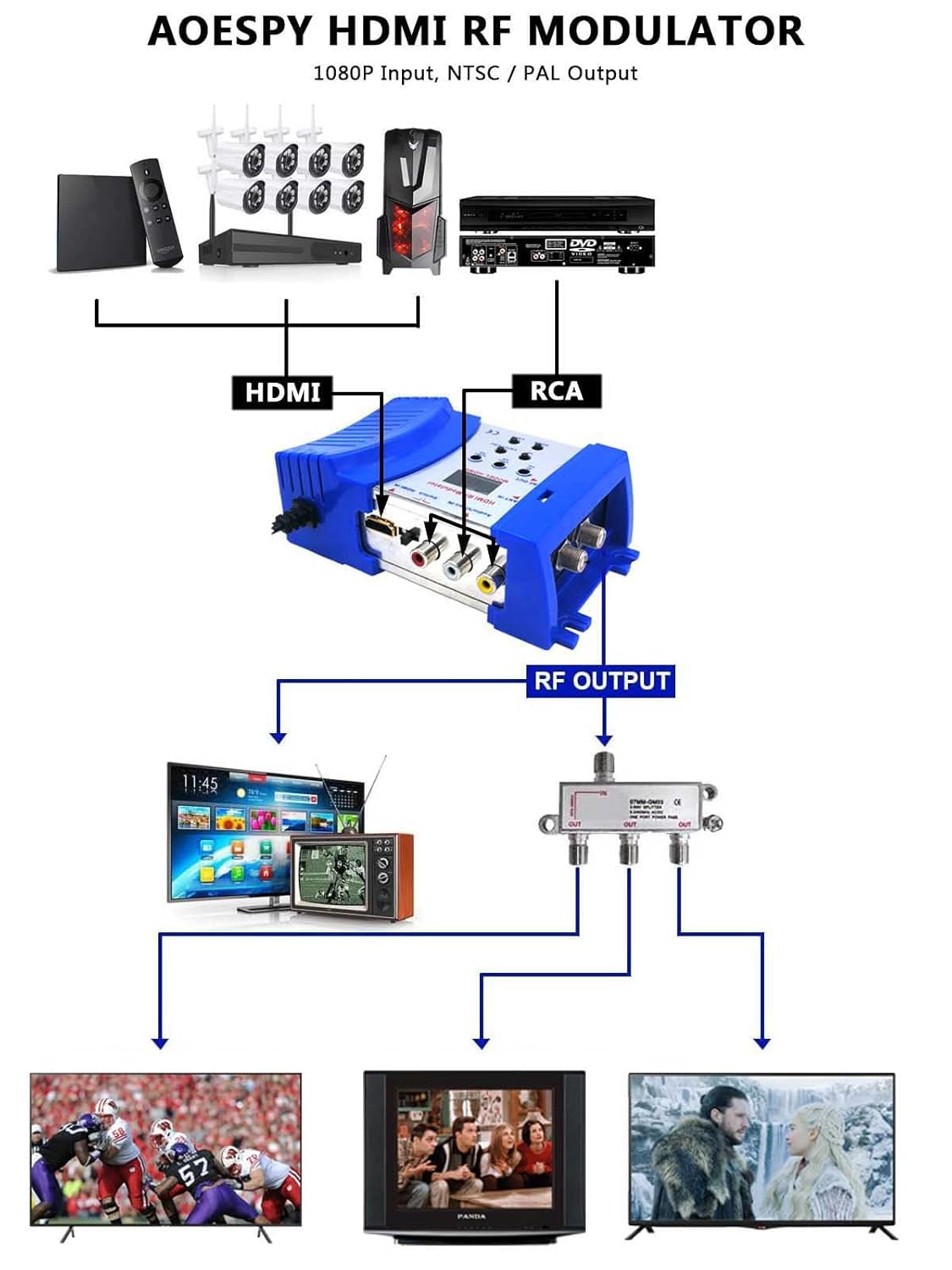
Figure 5.1: Diagram illustrating various connection scenarios for the AoeSpy HDMI RF Modulator, including HDMI and RCA inputs to RF output, and distribution to multiple TVs.
5.2 Basic Setup Steps
- Power Connection: Connect the provided power adapter to the modulator and plug it into a power outlet. The digital display on the modulator should illuminate.
- Input Device Connection:
- For HDMI Source: Connect an HDMI cable from your source device (e.g., Roku, Fire Stick, game console, PC) to the HDMI IN port on the modulator.
- For RCA (AV) Source: Connect RCA cables (yellow for video, white for left audio, red for right audio) from your source device (e.g., DVD player, VCR) to the Audio/Video IN ports on the modulator.
- RF Output Connection: Connect a coaxial cable from the RF OUT port on the modulator to the antenna/cable input (RF IN) on your television.
- Optional RF Loop-through: If you have an existing antenna or cable TV signal you wish to pass through, connect it to the ANT IN port on the modulator. This signal will be combined with the modulated signal and sent to the RF OUT.
- Television Tuning: Turn on your television and tune it to the desired channel (e.g., Channel 3 or 4 for NTSC, or a specific channel within the VHF/UHF range). You will need to match this channel on the modulator.
5.3 Visual Setup Guide
Video 5.1: This video demonstrates the physical connections and basic operation of the AoeSpy HDMI RF Modulator, showing how to connect input sources and adjust settings for output to a television.
6. Operating Instructions
Understanding the controls on your modulator is key to optimal performance.
6.1 Control Panel Layout

Figure 6.1: Detailed function diagram showing the labels and locations of all control buttons and adjustment knobs on the AoeSpy HDMI RF Modulator.
- Channel Display: Shows the currently selected output channel.
- DOWN Button: Decreases the output channel number.
- LOCK Button: Toggles between locked and unlocked states for channel and mode adjustments. Press to unlock before making changes, press again to lock.
- UP Button: Increases the output channel number.
- Mode Selection (CATV/TV/AU): Switches between channel groups (e.g., N1, N2, N3, N4 for NTSC M) or audio subcarrier settings. This button is also used to select between CATV (cable TV) and TV (broadcast) modes, and to adjust audio settings.
- Video Level Adjustment (Video Adj): Rotary knob to adjust video brightness. Turn counter-clockwise to brighten.
- Audio Level Adjustment (Audio Adj): Rotary knob to adjust audio volume. Turn counter-clockwise to increase volume.
- RF Level Adjustment (RF Adj): Rotary knob to adjust the strength of the RF output signal.
- Input Switch (Switch HDMI IN): Toggles between HDMI input and RCA (Audio/Video IN) input.
6.2 Channel Selection and Adjustment
- Unlocking Controls: Press the LOCK button to unlock the channel selection and mode settings. The display may flash or indicate an unlocked state.
- Selecting Output Channel: Use the UP and DOWN buttons to select the desired output channel. Ensure this matches the channel your television is tuned to. Refer to the NTSC M Channel Allocation Table (Figure 6.2) for specific frequency details.
- Mode/Channel Group Selection: The CATV/TV/AU button cycles through different channel groups (N1, N2, N3, N4 for NTSC M) and potentially audio subcarrier settings. Select the appropriate group for your region and desired channel.
- Adjusting Video/Audio/RF Levels: Use the corresponding rotary knobs (Video Adj, Audio Adj, RF Adj) to fine-tune the output signal quality.
- Locking Controls: Once settings are configured, press the LOCK button again to prevent accidental changes.
6.3 NTSC M Channel Allocation Table

Figure 6.2: Table detailing VHF/UHF operating frequencies for NTSC M channels, including video and audio carrier frequencies for different channel groups (N1, N2, N3, N4).
Note: "02" represents channel 2, while "02" in a channel group context (e.g., N1-02) refers to a specific frequency within that group.
7. Troubleshooting
- No Signal on TV:
- Ensure all cables (power, input, output) are securely connected.
- Verify the modulator is powered on and its digital display is active.
- Confirm the TV is tuned to the correct channel (e.g., Channel 3 or 4, or the specific channel set on the modulator).
- Check that the modulator's output channel matches the TV's tuned channel.
- Ensure the correct input source (HDMI or AV) is selected on the modulator using the Switch HDMI IN button.
- If using an HDMI source, try a different HDMI cable or source device to rule out issues with the source.
- If using RCA, ensure the yellow video cable and red/white audio cables are connected to the correct ports.
- Poor Picture Quality / Interference:
- Adjust the Video Adj knob on the modulator.
- Adjust the RF Adj knob to optimize signal strength. Too high or too low can cause issues.
- Ensure the coaxial cable is of good quality and properly shielded.
- Try a different output channel on the modulator and retune your TV. Some channels may have less interference in your area.
- Minimize other electronic devices near the modulator and coaxial cables to reduce potential interference.
- If connecting to multiple TVs via a splitter, consider using an amplified splitter if the signal is weak.
- No Audio:
- Adjust the Audio Adj knob on the modulator.
- Ensure audio cables (red/white RCA) are correctly connected if using AV input.
- Check TV volume and mute settings.
- Cannot Change Channel/Settings:
- Press the LOCK button to unlock the controls before attempting to change settings.
8. Maintenance
To ensure the longevity and optimal performance of your AoeSpy HDMI RF Modulator, follow these simple maintenance guidelines:
- Cleaning: Use a soft, dry cloth to clean the exterior of the device. Do not use liquid cleaners or aerosols, as they may damage the unit.
- Ventilation: Ensure the device is placed in a well-ventilated area to prevent overheating. Do not block any ventilation openings.
- Storage: When not in use for extended periods, store the modulator in a cool, dry place away from direct sunlight and extreme temperatures.
- Handling: Handle the device with care. Avoid dropping it or subjecting it to strong impacts.
9. Warranty and Support
For warranty information or technical support, please refer to the contact details provided with your purchase documentation or visit the official AoeSpy website. Keep your proof of purchase for warranty claims.