
Introduction
This manual provides detailed instructions for the installation, operation, and maintenance of your AUDIOTEK AT3500S 2 Channel Stereo Car Amplifier. The AT3500S is designed to deliver powerful and clear audio for your car's speaker system, featuring 3500 Watts maximum output, 2 Ohm stable operation, and a full-range Class A-B design. Please read this manual thoroughly before installation and use to ensure proper function and safety.
Key features include:
- 2 Channel Stereo Car Amplifier with 3500 Watts maximum power output.
- 2 Ohm Stable operation for flexible speaker configurations.
- Bridgeable MOSFET Amplifier design.
- Class A-B operation for balanced audio performance.
- Continuously variable low pass crossover and bass boost (0 to +18dB).
- Nickel-plated RCA and speaker level inputs.
- Remote turn-on/turn-off circuit.
- MOSFET Pulse Width Modulated (PWM) power supply.
- Thermal and speaker short protection circuitry.
- LED power and protection indicators.
Important Safety Information
WARNING:
- Always disconnect the vehicle's battery negative terminal before starting any electrical work.
- Ensure all wiring is properly routed and secured to prevent damage or short circuits.
- Use appropriate gauge wiring for power and ground connections as specified in the installation section.
- Do not mount the amplifier in locations exposed to direct sunlight, excessive heat, moisture, or dust.
- Ensure adequate ventilation around the amplifier to prevent overheating.
- Consult a professional car audio installer if you are unsure about any part of the installation process.
- Avoid operating the amplifier at excessively high volumes for prolonged periods, as this can damage hearing and speakers.
Setup and Installation
1. Unpacking
Carefully remove the amplifier from its packaging. Inspect the unit for any signs of damage that may have occurred during shipping. Retain the packaging for future use or shipping.
2. Mounting Location
Choose a mounting location that provides adequate ventilation and protection from moisture and direct heat. Common locations include under a seat, in the trunk, or behind a panel. Ensure the mounting surface is sturdy enough to support the amplifier's weight.
3. Wiring Connections
Proper wiring is crucial for optimal performance and safety. Refer to the diagrams and descriptions below.

Figure 1: Overview of the AUDIOTEK AT3500S amplifier's input and output panels. This image displays both the control panel with input level, bass boost, and crossover settings, and the power/speaker connection panel with battery, remote, ground, and speaker terminals.
3.1. Power Connections
- BATT+ (12V Power): Connect a heavy-gauge power cable (e.g., 4-gauge) directly from the positive terminal of your vehicle's battery. Install an in-line fuse holder (not supplied) within 18 inches (45 cm) of the battery.
- REMOTE (Remote Turn-On): Connect a remote turn-on wire from your head unit's remote output. This wire signals the amplifier to turn on when the head unit is active.
- GROUND: Connect a heavy-gauge ground cable (e.g., 4-gauge) from the amplifier's ground terminal to a clean, unpainted metal surface on the vehicle's chassis. Ensure a good electrical connection.
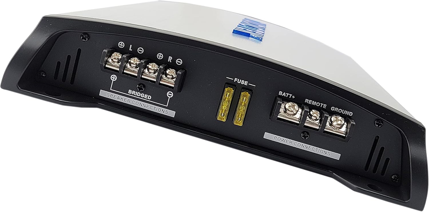
Figure 2: Close-up view of the power and speaker connection terminals on the AUDIOTEK AT3500S amplifier. This includes the BATT+, REMOTE, GROUND terminals, fuse slots, and the LEFT/RIGHT speaker output terminals, along with the BRIDGED connection option.
3.2. Speaker Connections
Connect your speakers to the "SPEAKER CONNECTIONS" terminals. The AT3500S supports both stereo and bridged mono configurations.
- Stereo Mode: Connect the left speaker to the L+ and L- terminals, and the right speaker to the R+ and R- terminals. Ensure correct polarity.
- Bridged Mode: For higher power output to a single subwoofer, connect the speaker to the L+ and R- terminals. Refer to the amplifier's specifications for minimum impedance in bridged mode.
3.3. Input Connections
The amplifier offers both Low Level (RCA) and High Level inputs.
- Low Level Inputs (RCA): For best audio quality, connect RCA cables from your head unit's pre-out outputs to the amplifier's "LOW LEVEL INPUTS" (LEFT and RIGHT RCA jacks).
- High Level Inputs: If your head unit does not have RCA pre-outs, use the high-level input connector. Connect the speaker wires from your head unit to the provided high-level input harness.

Figure 3: Detailed view of the input and control panel of the AUDIOTEK AT3500S amplifier. This panel features the HIGH LEVEL and LOW LEVEL (RCA) inputs, INPUT LEVEL gain control, BASS BOOST knob, LOW PASS FREQ. crossover control, MODE switch, REMOTE bass knob port, and POWER/PROTECTION LED indicators.
3.4. Remote Bass Knob Connection
Connect the included remote bass knob to the "REMOTE" port on the amplifier's control panel. This allows for convenient adjustment of bass levels from the driver's seat.
4. Initial Settings
- INPUT LEVEL (Gain): Start with the INPUT LEVEL control set to minimum (MIN). Gradually increase this setting until the desired volume is achieved without distortion. This matches the amplifier's input sensitivity to your head unit's output.
- BASS BOOST: Adjust the BASS BOOST knob from 0 to +18dB to enhance low-frequency response. Use sparingly to avoid distortion.
- LOW PASS FREQ. (Crossover): This amplifier features a continuously variable low pass crossover. Set the frequency (e.g., 80Hz-120Hz for subwoofers) to filter out high frequencies from reaching your speakers, ensuring only bass frequencies are reproduced.
- MODE: Select the appropriate mode (e.g., Low Pass, Full Range) based on your speaker configuration and desired sound.
Operating Instructions
1. Powering On/Off
The amplifier will automatically turn on when your head unit is powered on, provided the remote turn-on wire is correctly connected. The "POWER" LED indicator will illuminate blue. When the head unit is turned off, the amplifier will power down.
2. Adjusting Audio Settings
Once the amplifier is powered on, you can fine-tune the audio settings:
- Volume: Control the overall system volume using your head unit.
- Input Level: If you experience distortion at higher volumes, slightly reduce the INPUT LEVEL on the amplifier. If the sound is too low even at maximum head unit volume, gradually increase the INPUT LEVEL.
- Bass Boost: Use the BASS BOOST control to add more emphasis to bass frequencies. Adjust to taste, ensuring the sound remains clear and undistorted.
- Crossover (LOW PASS FREQ.): Adjust the LOW PASS FREQ. to optimize the sound for your speakers. For subwoofers, a typical range is 80Hz-120Hz. Experiment to find the best setting for your system.
- Remote Bass Knob: Use the wired remote bass knob for quick adjustments to the bass level from your listening position.
The "PROTECTION" LED indicator will illuminate red if the amplifier detects a fault (e.g., short circuit, overheating). If this occurs, turn off your system immediately and refer to the Troubleshooting section.
Maintenance
1. Cleaning
Periodically clean the amplifier's exterior with a soft, dry cloth. Do not use harsh chemicals or abrasive cleaners. Ensure the heatsink fins are free from dust and debris to maintain proper cooling.
2. Fuse Replacement
The amplifier is equipped with internal fuses for protection. If a fuse blows, the amplifier will not power on. Replace blown fuses only with fuses of the exact same type and rating (refer to the specifications or the fuse holder itself). Using an incorrect fuse can cause serious damage to the amplifier or your vehicle's electrical system.
3. General Care
Ensure all wiring connections remain secure. Loose connections can lead to poor performance or damage. Avoid placing objects on top of the amplifier that could obstruct airflow.
Troubleshooting Guide
If you experience problems with your amplifier, refer to the following common issues and solutions:
| Problem | Possible Cause | Solution |
|---|---|---|
| No Power / Power LED Off |
|
|
| No Sound / Distorted Sound |
|
|
| Protection LED On (Red) |
|
|
| Excessive Noise (Hiss, Whine) |
|
|
Specifications
| Feature | Detail |
|---|---|
| Brand | AUDIOTEK |
| Model Name | AT3500S |
| Speaker Maximum Output Power | 3500 Watts |
| Number of Audio Channels | 2.0 |
| Audio Output Mode | Stereo |
| Connectivity Technology | RCA |
| Mounting Type | Surface Mount |
| Additional Features | Protection (Thermal, Speaker Short) |
| Controller Type | Remote Control (Bass Knob) |
| Power Source | Corded Electric (12V DC) |
| Operation | Class A-B |
| Stability | 2 Ohm Stable |
| Bass Boost | 0 to +18dB (Continuously Variable) |
| Crossover | Low Pass (Continuously Variable) |
Warranty Information
AUDIOTEK products are manufactured to high-quality standards. This product is covered by a limited warranty against defects in materials and workmanship. The specific terms and duration of the warranty may vary by region and retailer. Please retain your proof of purchase for warranty claims. For detailed warranty information, please refer to the warranty card included with your product or contact AUDIOTEK customer support.
Customer Support
If you have any questions, require technical assistance, or encounter issues not covered in this manual, please contact AUDIOTEK customer support. Contact information can typically be found on the official AUDIOTEK website or on the product packaging.
For online resources, visit: www.audiotek.com (Note: This is a placeholder URL. Please refer to actual product documentation for correct support links.)