1. Product Overview
The Temank Growatt 5000W SPF 5000ES Solar Inverter is an all-in-one hybrid power solution designed for off-grid applications. It converts 48V DC power to 220V AC (single phase) and features a built-in 100A MPPT solar charge controller. This inverter is compatible with various battery types, including lead-acid and lithium, and can also operate without a battery. It supports parallel operation for capacity expansion up to 30kW, allowing up to 6 units to work together, including support for three-phase equipment when batteries are connected.
Key functionalities include flexible scheduling for inverter charging and discharging, and compatibility with both mains voltage and generator power. Optional WiFi/GPRS remote monitoring is available for real-time system status updates via mobile or web.

Figure 1.1: System Diagram of the Growatt SPF 5000ES Inverter.
2. Product Features
- Pure Sine Wave Output: Provides stable and clean power suitable for sensitive electronics.
- Integrated MPPT Controller: Built-in 100A MPPT solar charge controller maximizes solar power harvesting.
- High PV Input: Supports a maximum PV power of 6000W and a maximum PV input VOC of 450V DC.
- Battery Compatibility: Works with 48V lead-acid, lithium, and user-defined battery types, or can operate without a battery.
- Parallel Operation: Expandable up to 30kW by connecting up to 6 units in parallel, supporting single-phase or three-phase loads (with battery).
- Flexible Charging Modes: Three optional charging modes: Solar First, Solar and Utility, or Only Solar.
- Output Priority Modes: Four available output modes: Solar First, Utility First, SBU Priority, and SUB Priority.
- Communication Ports: Equipped with WIFI/GPRS, USB, CAN, and RS485 communication ports for monitoring and control.
- Comprehensive Protections: Includes low voltage, overheat, short circuit, overload, over current, and auto frequency range protection.

Figure 2.1: Growatt 5000W Solar Hybrid Inverter Features.
3. Unpacking and Inspection
Upon receiving your Growatt SPF 5000ES Solar Inverter, carefully unpack the unit and inspect its contents. Ensure all components are present and undamaged. If any items are missing or damaged, contact your supplier immediately.
3.1. Package Contents
The standard package includes:
- Growatt SPF 5000ES Inverter
- MPPT Controller (integrated)
- User Manual/Installation Guide
- Parallel Communication Cable
- Current Sharing Cable
- USB Communication Cable
- Software CD

Figure 3.1: Growatt SPF 5000ES Inverter Package Contents.
3.2. Unpacking Video Guide
Video 3.1: Unpacking and inspecting the Growatt SPF 5000ES inverter. This segment demonstrates how to safely open the packaging and verify the included components.
4. Appearance and Ports
Familiarize yourself with the inverter's external components and connection ports before installation.
4.1. Front Panel Description

Figure 4.1: Front Panel of the Growatt SPF 5000ES Inverter.
- Status Indicator: Displays the operational status of the inverter.
- Fault Indicator: Illuminates to indicate a system fault or error.
- Charging Indicator: Shows the battery charging status.
- LCD Display Screen: Provides real-time system information and allows for configuration.
- Function Buttons: Used for navigating menus and adjusting settings.
4.2. Rear Panel and Connection Ports

Figure 4.2: Rear Panel and Connection Ports.
- AC Input Port: For connecting to the utility grid or a generator.
- WIFI/GPRS Communication Port: For optional remote monitoring modules.
- USB Communication Port: For local monitoring and firmware updates.
- Dry Contact Port: For external control signals.
- PV Input Port: For connecting solar panel arrays.
- CAN Communication Port: For parallel communication between inverters.
- RS485 Communication Port: For external communication devices.
- Power On/Off Switch: Main power control for the inverter.
- Battery Input Port: For connecting to the battery bank.
- Parallel Communication Port: For connecting multiple inverters in parallel.
- Current Sharing Port: For current balancing in parallel systems.
- AC Output Port: For connecting to household loads.
- Circuit Breaker: Provides overcurrent protection for the AC output.
5. Installation Guidelines
Proper installation is crucial for the safe and efficient operation of your Growatt inverter. Please follow these guidelines carefully.
5.1. Safety Precautions
- Do not mount the inverter on flammable construction materials.
- Ensure the mounting surface is solid and can support the inverter's weight.
- Install the inverter at eye level to easily read the LCD display.
- The ambient temperature should be between 0°C and 55°C for optimal operation.

Figure 5.1: Do not mount on flammable materials.

Figure 5.2: Mount on a solid surface.
5.2. Mounting Position and Clearance
The recommended installation position is to adhere the inverter to the wall vertically. Ensure sufficient clearance around the unit for proper heat dissipation and ease of wiring.
- Maintain at least 20 cm clearance on the sides.
- Maintain at least 50 cm clearance above and below the unit.

Figure 5.3: Recommended Installation Clearances.
5.3. Installation Video Guide
Video 5.1: Installation presentation for the Growatt SPF 5000ES inverter, covering tools, safety, mounting, and clearances.
6. Wiring Connections
All wiring should be performed by a qualified electrician in accordance with local electrical codes and regulations. Ensure all power sources are disconnected before making any connections.
6.1. Battery Connection
Connect the 48V battery bank to the Battery Input Port. Use 2AWG size cables for optimal performance. Ensure correct polarity (+ to + and - to -).

Figure 6.1: Battery Input Port.
6.2. AC Input Connection
Connect the utility grid or generator to the AC Input Port. Use 8AWG size cables. The inverter is designed for 220V AC single-phase input.

Figure 6.2: AC Input Port.
6.3. AC Output Connection
Connect your household loads to the AC Output Port. Use 8AWG size cables. The inverter provides 220V AC single-phase output.

Figure 6.3: AC Output Port.
6.4. PV Input Connection
Connect your solar panel array to the PV Input Port. Ensure the maximum PV input voltage (VOC) does not exceed 450V DC and the maximum input current is 18A. Use 10-12AWG PV wires.

Figure 6.4: PV Input Port.
6.5. Communication Module Installation
For remote monitoring, install the optional WIFI-F or GPRS-F communication module into the designated port.

Figure 6.5: Installing the WIFI-F Communication Module.
6.6. Wiring Connection Video Guide
Video 6.1: Detailed guide on connecting battery, AC input, AC output, and PV input cables to the Growatt SPF 5000ES inverter.
7. Operation and Settings
This section covers basic operation and how to configure key settings using the LCD display and function buttons.
7.1. Powering On/Off
To power on the inverter, ensure all connections are secure, then switch the Power On/Off switch to the 'ON' position.

Figure 7.1: Powering On the Inverter.
7.2. LCD Display Navigation
Use the 'ESC', 'UP', 'DOWN', and 'ENTER' buttons to navigate through the LCD display menus and adjust settings.

Figure 7.2: LCD Display and Navigation Buttons.
7.3. Key Programmable Settings
The inverter offers several programmable settings to optimize its operation for your specific setup.
- Program 01: Output Source Priority
This setting defines the priority of power sources for your loads. Options include: Solar First (SOL), Utility First (UEI), SBU Priority (SBU), and SUB Priority (SUB). - Program 05: Battery Type
Select the type of battery connected to the inverter. Options typically include Flooded (FLD), AGM, User-defined (USE), and Lithium (LI). For lithium batteries, consult the compatibility list and set the communication protocol. - Program 14: Charger Source Priority
This setting defines the priority of charging sources for the battery. Options include: Solar First (CSO), Grid First (CUE), Solar and Grid (SNU), and Only Solar (OSO). - Program 19: Bulk Charging Voltage (CV Voltage)
Adjust the bulk charging voltage for user-defined battery types, typically ranging from 48V to 58.4V. - Program 20: Floating Charging Voltage
Adjust the floating charging voltage for user-defined battery types, typically ranging from 48V to 58.4V. - Program 21: Low DC Cut-off Voltage
Set the low DC cut-off voltage for user-defined battery types, typically ranging from 40V to 48V. - Program 23: AC Output Mode (Parallel Operation)
For parallel systems, select 'PAL' for single-phase parallel operation. For three-phase parallel operation, select '3P1' for L1 phase, '3P2' for L2 phase, and '3P3' for L3 phase.

Figure 7.3: Output Source Priority (Solar First).

Figure 7.4: Battery Type Selection.
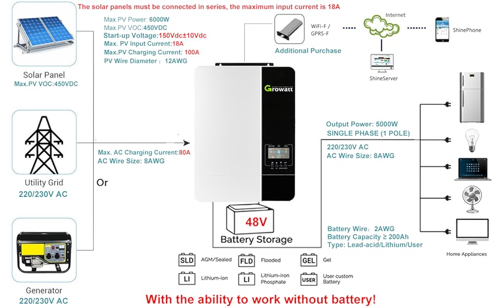
Figure 7.5: Charger Source Priority Modes.
7.4. Operation and Settings Video Guide
Video 7.1: Demonstration of navigating the LCD display and configuring various operational settings on the Growatt SPF 5000ES inverter.
8. Troubleshooting
This section provides common problems, their explanations, and recommended solutions. For more detailed troubleshooting, refer to the full user manual.

Figure 8.1: Troubleshooting Guide.
8.1. Troubleshooting Video Guide
Video 8.1: Overview of common troubleshooting steps and fault codes for the Growatt SPF 5000ES inverter.
9. Technical Specifications
| Specification | Value |
|---|---|
| Product Dimensions | 19.09 x 12.99 x 5.31 inches |
| Item Weight | 30.8 pounds |
| Item Model Number | Growatt (SPF 5000ES) |
| Frequency | 60 Hz |
| Color | Black, White |
| Manufacturer | Temank |
| Recommended Uses | Off-grid, Recreational Vehicle, Boat, Backup power |
| Power Source | Battery Powered |
| Wattage | 5000W (Output), 6000W (Max PV Power) |
| Battery Capacity | ≥200 Amp Hours (Recommended) |
| Max. PV Input Current | 18A |
| Max. PV Input VOC | 450V DC |
| Max PV Charging Current | 100A |
10. Warranty and Support
For detailed warranty information, technical support, and service inquiries, please refer to the official documentation provided with your product or contact Temank Growatt customer service directly. Keep your purchase receipt for warranty claims.