1. Introduction
Thank you for choosing the Ingco DCM2001 Digital Clamp Meter. This device is designed for safe and accurate measurement of AC/DC voltage, AC current, resistance, and diode testing. It also features non-contact voltage (NCV) detection and low input impedance to prevent ghost voltage readings. This manual provides essential information for the proper operation and maintenance of your clamp meter. Please read it thoroughly before use and retain it for future reference.
2. Safety Information
To ensure safe operation, observe the following safety precautions:
- Always inspect the meter and test leads for damage before use. Do not use if damaged.
- Do not apply more than the rated voltage, as marked on the meter, between the terminals or between any terminal and ground.
- Use extreme caution when working with voltages above 60V DC or 30V AC RMS, as these pose a shock hazard.
- Keep fingers behind the finger guards on the test leads during measurements.
- Do not operate the meter in explosive gas, vapor, or dust environments.
- Ensure the function switch is in the correct position for the desired measurement before connecting to the circuit.
- Disconnect the test leads from the circuit before changing functions.
- Replace batteries immediately when the low battery indicator appears to ensure accurate readings.
- Adhere to local and national safety codes.
3. Product Overview
The Ingco DCM2001 is a compact and versatile digital clamp meter designed for electrical professionals and DIY enthusiasts. Its ergonomic design allows for comfortable one-hand operation. Key features include a digital display, 200 Amp AC current measurement capability, and accurate readings for various electrical parameters.
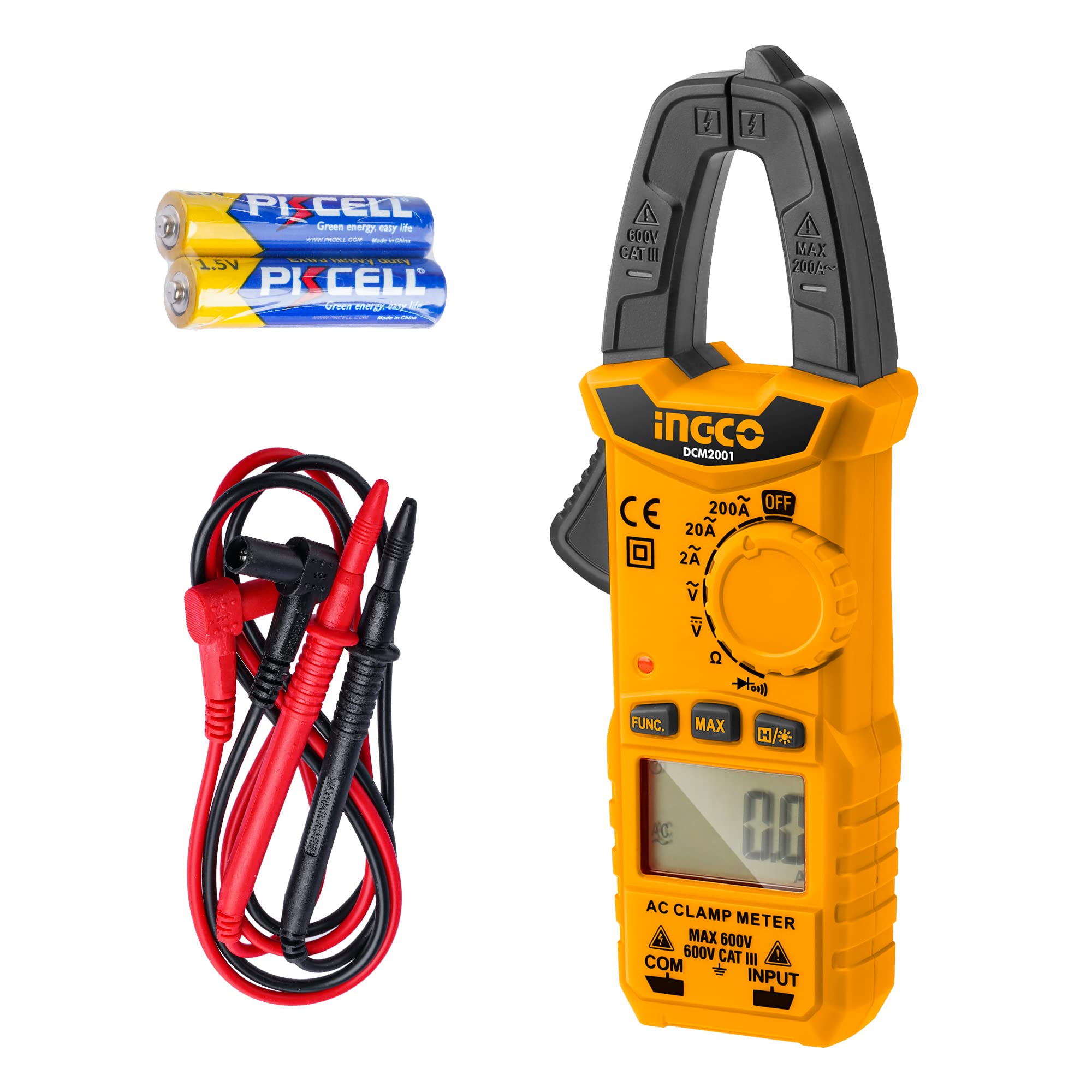
Figure 1: Front view of the Ingco DCM2001 Digital Clamp Meter, showing the clamp jaw, function dial, display, and input terminals.
Components:
- Clamp Jaw: For non-contact AC current measurement.
- Function Dial: Selects measurement modes (Voltage, Current, Resistance, Diode, NCV).
- LCD Display: Shows measurement readings, units, and indicators.
- Input Terminals: For connecting test leads for voltage, resistance, and diode measurements.
- Data Hold Button: Freezes the current reading on the display.
- Backlight Button: Activates/deactivates the display backlight.
4. Setup
4.1 Battery Installation
The Ingco DCM2001 requires batteries for operation. Ensure correct polarity when installing.
- Locate the battery compartment cover on the back of the meter.
- Use a screwdriver to remove the screw securing the cover.
- Remove the cover.
- Insert the required alkaline batteries, observing the polarity markings (+ and -).
- Replace the battery compartment cover and secure it with the screw.
Note: The meter comes with batteries included. If the low battery indicator appears on the display, replace the batteries promptly.
5. Operating Instructions
5.1 Power On/Off
Rotate the function dial from the "OFF" position to any desired measurement function to power on the meter. To power off, rotate the dial back to the "OFF" position.
5.2 AC Current Measurement (Clamp Jaw)
This function allows for non-contact measurement of AC current.
- Rotate the function dial to the "A~" (AC Current) position.
- Press the jaw trigger to open the clamp jaw.
- Enclose only one conductor (wire) within the clamp jaw. Ensure the jaw is fully closed.
- Read the AC current value on the LCD display.
Caution: Do not attempt to measure current on multiple conductors simultaneously, as this will result in an inaccurate reading (near zero) due to opposing magnetic fields.
5.3 DC/AC Voltage Measurement
To measure voltage, use the provided test leads.
- Insert the red test lead into the "VΩ" terminal and the black test lead into the "COM" terminal.
- Rotate the function dial to the "V~" (AC Voltage) or "V-" (DC Voltage) position.
- Connect the test probes in parallel to the circuit or component you wish to measure.
- Read the voltage value on the LCD display.
Warning: Do not exceed the maximum input voltage rating of 600V.
5.4 Resistance Measurement
To measure resistance, ensure the circuit is de-energized.
- Insert the red test lead into the "VΩ" terminal and the black test lead into the "COM" terminal.
- Rotate the function dial to the "Ω" (Resistance) position.
- Ensure the circuit or component under test is completely de-energized.
- Connect the test probes across the component.
- Read the resistance value on the LCD display.
Important: Do not measure resistance on live circuits.
5.5 Diode Test
This function checks the forward voltage drop of a diode.
- Insert the red test lead into the "VΩ" terminal and the black test lead into the "COM" terminal.
- Rotate the function dial to the "Diode" symbol position.
- Connect the red probe to the anode and the black probe to the cathode of the diode.
- The display will show the forward voltage drop (typically 0.5V to 0.8V for silicon diodes). Reversing the probes should show "OL" (Open Loop) for a good diode.
5.6 Non-Contact Voltage (NCV) Detection
The NCV function detects the presence of AC voltage without direct contact.
- Rotate the function dial to the "NCV" position.
- Bring the top tip of the meter near a live AC voltage source (e.g., a live wire or outlet).
- The meter will emit an audible beep and the NCV indicator light will flash, indicating the presence of AC voltage. The frequency of beeps and flashes increases with stronger voltage.
Note: NCV detection is for indication only and should not be used as the sole method to determine if a circuit is de-energized.
5.7 Data Hold Function
Press the "HOLD" button to freeze the current reading on the display. Press it again to release the hold function.
5.8 Backlight Function
Press the "Backlight" button to turn on the display backlight for better visibility in low-light conditions. Press it again to turn off the backlight.
6. Maintenance
6.1 Cleaning
Wipe the meter with a dry, soft cloth. Do not use abrasives or solvents. Keep the clamp jaw free of dust and debris.
6.2 Battery Replacement
When the low battery indicator appears on the display, replace the batteries as described in Section 4.1. Remove batteries if the meter will not be used for an extended period to prevent leakage.
6.3 Calibration
The meter is factory calibrated. For professional calibration services, contact Ingco customer support or an authorized service center.
7. Troubleshooting
| Problem | Possible Cause | Solution |
|---|---|---|
| Meter does not power on. | Dead or incorrectly installed batteries. | Check battery polarity or replace batteries. |
| "OL" (Overload) displayed. | Measurement exceeds the meter's range. | Select a higher range if available, or ensure the measured value is within specifications. |
| Inaccurate AC current reading. | Multiple conductors in the clamp jaw. | Ensure only one conductor is enclosed in the clamp jaw. |
| No NCV detection. | Voltage too low or meter not close enough to source. | Ensure the meter tip is close to the AC source. Verify the source is live. |
8. Specifications
| Parameter | Value |
|---|---|
| Model | DCM2001 |
| Manufacturer | Ingco |
| DC Voltage Range | 0.1V - 600V (Accuracy: 0.5% + 5 digits) |
| AC Voltage Range | 0.1V - 600V (Accuracy: 1.0% + 5 digits) |
| AC Current Range | 10mA - 200A (Accuracy: 2.5% + 8 digits) |
| Resistance Range | 0Ω - 20kΩ (Accuracy: 1.0% + 3 digits) |
| Display Count | 2000 counts |
| Diode Test | Yes |
| Non-Contact Voltage (NCV) | Yes |
| Power Source | Battery (Alkaline) |
| Batteries Included | Yes |
| Product Dimensions | 19.05 x 3.3 x 7.11 cm |
| Item Weight | 100 g |
| Safety Standard | IEC 61010-1:2000-1 |
9. Warranty and Support
Ingco products are manufactured to high-quality standards. For warranty information, please refer to the warranty card included with your product or visit the official Ingco website. For technical support, troubleshooting assistance, or service inquiries, please contact Ingco customer service through their official channels.
Website: www.ingco.com


