Hantek 6000BE/6102BE USB Digital Storage Oscilloscope User Manual
Model: 6102BE
1. Introduction
This manual provides detailed instructions for the safe and effective operation of your Hantek 6000BE/6102BE USB Digital Storage Oscilloscope. Please read this manual thoroughly before using the device to ensure proper functionality and to prevent damage.
Key Features:
- 2 Channels
- 100MHz Bandwidth
- 10mV-5V Gain Range
- 250MS/s Max. Sample Rate
- 1MΩ 25pF Input Impedance
- Multiple Trigger Modes: Auto, Normal, Single
- Trigger Types: Rising edge, falling edge
- Mathematical Functions: FFT, addition, subtraction, multiplication, division
- Waveform Display Options: Port/line, waveform average, persistence, intensity
2. Package Contents
Verify that all items listed below are included in your package. If any items are missing or damaged, please contact your vendor.
- Hantek 6000BE/6102BE USB Digital Storage Oscilloscope Unit
- 2 x Passive Probes
- Software CD
- User Manual (this document)
- USB Cable

Figure 2.1: Included accessories and oscilloscope unit in packaging.
3. Product Overview
3.1. Physical Dimensions
The Hantek 6000BE/6102BE oscilloscope has compact dimensions, making it suitable for various workspaces.
- Dimensions: 20.7 x 12.3 x 3.7 cm (8.15 x 4.84 x 1.46 inches)
- Weight: 805 g (1.77 lbs)

Figure 3.1: Physical dimensions of the Hantek 6000BE/6102BE oscilloscope.
3.2. Front and Rear Panel Layout
Familiarize yourself with the various ports and controls on the oscilloscope.
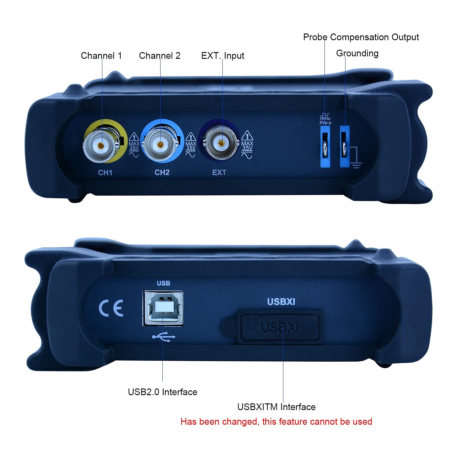
Figure 3.2: Detailed view of the front and rear panel connections.
- Front Panel:
- Channel 1 (CH1) Input: BNC connector for analog input.
- Channel 2 (CH2) Input: BNC connector for analog input.
- External (EXT) Input: BNC connector for external trigger input.
- Probe Compensation Output: Used for calibrating probes.
- Grounding Terminal: For connecting probe ground clips.
- USB 2.0 Interface: For connecting to a PC.
- USBXI Interface: (Note: This feature may be changed or unavailable on some models).
- Rear Panel:
- Power Input: For connecting the power cable.
- USB Port: For connecting to a PC for data transfer and remote control.
4. Setup
4.1. Initial Connection
- Connect the power cable to the power input on the rear panel of the oscilloscope and to a suitable power outlet.
- Connect the USB cable from the oscilloscope's USB 2.0 interface (front panel) or the USB port (rear panel) to your computer.
- Install the necessary software drivers from the included CD or the manufacturer's website.
4.2. Probe Connection and Calibration
The oscilloscope comes with two passive probes. Proper connection and calibration are essential for accurate measurements.
- Connect a probe to either the CH1 or CH2 BNC input on the front panel.
- Connect the probe's ground clip to the grounding terminal on the front panel.
- Connect the probe tip to the Probe Compensation Output terminal.
- Power on the oscilloscope.
- Adjust the probe compensation (usually a small screw on the probe body) until the displayed square wave is flat-topped, without overshoot or undershoot.

Figure 4.1: Hantek 6000BE/6102BE oscilloscope with probes connected to input channels.
5. Operating Instructions
5.1. Powering On and Basic Display
- Press the power button located on the front panel to turn on the oscilloscope.
- Allow a few moments for the device to boot up and display the main waveform interface.
5.2. Front Panel Controls
The front panel features various knobs and buttons for controlling vertical, horizontal, and trigger settings, as well as general menu navigation.
- Vertical Controls: Adjust voltage per division and vertical offset for each channel.
- Horizontal Controls: Adjust time per division and horizontal offset.
- Trigger Controls: Set trigger level, mode (Auto, Normal, Single), and type (rising/falling edge).
- Menu Buttons: Navigate through various settings and functions displayed on the screen.
5.3. Using Test Signals
The oscilloscope can display various signals, including internal test signals and external signals from devices like component testers.
- Connect a probe to the signal source (e.g., the 1kHz square wave test signal output on the oscilloscope itself, or an external signal generator).
- Adjust the vertical and horizontal controls to achieve a clear and stable waveform display.
- Use the 'Auto Set' function for quick waveform optimization.
5.4. Measurements and Analysis
The oscilloscope offers various measurement functions and analysis tools, including FFT for frequency domain analysis.
- Access measurement menus to display parameters like frequency, period, peak-to-peak voltage, mean voltage, etc.
- Utilize the Math functions (FFT, addition, subtraction, multiplication, division) for advanced signal analysis.
Video 5.1: Demonstration of Hantek Oscilloscope features and basic operation. (Note: The oscilloscope model shown in this video is DSO5072P, which may differ slightly from the 6000BE/6102BE model in appearance, but the operational principles are similar.)
6. Maintenance
6.1. General Care
- Keep the oscilloscope in a clean, dry environment, away from direct sunlight, dust, and excessive humidity.
- Avoid exposing the device to strong vibrations or impacts.
- Do not block the ventilation openings on the device.
6.2. Cleaning
- Use a soft, dry cloth to clean the exterior of the oscilloscope.
- For stubborn dirt, lightly dampen the cloth with water or a mild, non-abrasive cleaner.
- Do not use harsh chemicals, solvents, or abrasive cleaners, as these can damage the casing and screen.
7. Troubleshooting
7.1. No Power
- Ensure the power cable is securely connected to both the oscilloscope and the power outlet.
- Verify that the power outlet is functional.
- Check the power button on the front panel to ensure it is pressed.
- Check probe connections to the input channels and the signal source.
- Ensure the input channel is enabled in the oscilloscope settings.
- Adjust the vertical (Volts/Div) and horizontal (Time/Div) settings to an appropriate range for the signal being measured.
- Verify trigger settings (level, mode) are correctly configured. Try the 'Auto Set' function.
7.3. Driver Issues (Windows 10)
- If experiencing driver issues on Windows 10, please contact Hantek support via Amazon for assistance with downloading and installing the correct drivers.
8. Specifications
| Feature | Specification |
|---|
| Model | Hantek 6102BE |
| Channels | 2 |
| Bandwidth | 100MHz |
| Input Impedance | 1MΩ 25pF |
| Max. Sample Rate | 250MS/s |
| Coupling | AC/DC/GND |
| Vertical Resolution | 8Bit |
| Gain Range | 10mV-5V |
| DC Accuracy | ±3% |
| Timebase Range | 4ns-5ks |
| Input Protection | Diode clamping |
| Trigger Mode | Auto, Normal, Single |
| Trigger Type | Rising edge, falling edge |
| Trigger Source | CH1, CH2, EXT |
| Math Functions | FFT, addition, subtraction, multiplication, division |
| Cursor Measurement | Yes (Frequency, Voltage) |
| Product Dimensions | 20.7 x 12.3 x 3.7 cm |
| Product Weight | 805 g |
9. Warranty and Support
Specific warranty information is not provided in the product details. For warranty claims, technical support, or service inquiries, please contact Hantek customer service through your purchase platform or refer to the official Hantek website for contact details.
