1. Introduction
The C-LOGIC 5100 is a manual ranging digital multimeter designed for precise electrical measurements. This versatile instrument is capable of measuring AC/DC voltage, AC/DC current, resistance, capacitance, frequency, temperature, and transistor hFE. It features a durable rubber housing for enhanced grip and comfort, along with a hinged bracket for convenient table-top operation. This manual provides essential information for the safe and effective use of your C-LOGIC 5100 Digital Multimeter.
2. Safety Information
Always observe the following safety precautions when operating the C-LOGIC 5100 Digital Multimeter to prevent personal injury or damage to the instrument:
- Ensure the multimeter is set to the correct function and range before connecting the test leads to any circuit.
- Do not exceed the maximum input values specified for each function. The C-LOGIC 5100 is rated for CAT III 600V.
- Disconnect the test leads from the circuit before changing functions or ranges.
- Inspect test leads for damaged insulation or exposed metal before each use. Replace damaged leads immediately.
- Do not operate the multimeter if it appears damaged or if the case is open.
- Exercise extreme caution when working with voltages above 60V DC or 30V AC RMS, as these pose a shock hazard.
- Remove test leads from the multimeter before opening the battery compartment or fuse cover.
3. Product Features
The C-LOGIC 5100 Digital Multimeter incorporates several features designed for user convenience and functionality:
- Rubber Housing: Provides improved grip and protection against accidental drops.
- Hinged Bracket: Allows the multimeter to stand upright for hands-free operation on a workbench.
- Measurement Capabilities: AC/DC Voltage, AC/DC Current, Resistance, Capacitance, Frequency, Temperature, and Transistor hFE.
- Display Counts: 2000-count digital display for clear readings.
- Auto Power OFF (APO): Automatically turns off the device after a period of inactivity to conserve battery life.
- Data Hold: Freezes the displayed reading for convenient recording.
- Low Battery Display (LBD): Indicates when the battery needs replacement.
- Diode Test and Continuity Buzzer: For testing diodes and checking circuit continuity.
4. Components and Controls

Figure 1: Front view of the C-LOGIC 5100 Digital Multimeter, showing the display, function selector, and input jacks.
Familiarize yourself with the main components of your multimeter:
- LCD Display: Shows measurement readings, units, and function indicators.
- Function/Range Selector Dial: Used to select the desired measurement function and range.
- HOLD Button: Press to freeze the current reading on the display. Press again to release.
- ON/OFF Switch: Powers the multimeter on or off.
- Input Jacks:
- VΩHzTemp: Positive input for voltage, resistance, frequency, temperature, capacitance, diode, and continuity measurements.
- COM: Common (negative) input for all measurements.
- mA: Positive input for current measurements up to 200mA.
- 10A: Positive input for current measurements up to 10A (MAX 30 sec. every 15 min.). This input is fused.
- hFE Socket: For testing transistor hFE (DC current gain).
5. Setup
5.1 Battery Installation
The C-LOGIC 5100 requires one 9V 6F22 battery (not included). To install or replace the battery:
- Ensure the multimeter is turned OFF and disconnect all test leads from the input jacks.
- Locate the battery compartment cover on the rear of the unit.
- Unscrew the retaining screw(s) and carefully remove the cover.
- Connect the 9V battery to the battery clip, observing correct polarity.
- Place the battery into the compartment and replace the cover, securing it with the screw(s).
5.2 Test Lead Connection
Proper connection of test leads is crucial for accurate and safe measurements:
- For most measurements (voltage, resistance, capacitance, frequency, temperature, diode, continuity), insert the red test lead into the VΩHzTemp jack and the black test lead into the COM jack.
- For current measurements up to 200mA, insert the red test lead into the mA jack and the black test lead into the COM jack.
- For current measurements up to 10A, insert the red test lead into the 10A jack and the black test lead into the COM jack.
6. Operating Instructions

Figure 2: The C-LOGIC 5100 Digital Multimeter actively measuring voltage in an electrical panel.
Follow these general steps for making measurements:
- Turn the multimeter ON using the ON/OFF switch.
- Select the desired function and appropriate range using the rotary dial. If unsure of the range, start with the highest range and work downwards.
- Connect the test leads to the circuit or component under test.
- Read the measurement value on the LCD display.
- After measurement, disconnect the test leads and turn the multimeter OFF.
6.1 Specific Measurement Functions
- DC Voltage (V=): Select the V= range. Connect the red lead to the positive side and the black lead to the negative side of the DC voltage source in parallel.
- AC Voltage (V~): Select the V~ range. Connect the test leads across the AC voltage source in parallel. Polarity is not critical for AC voltage.
- DC Current (A=): Select the A= range (mA or 10A jack). Disconnect power to the circuit. Open the circuit where current is to be measured and connect the multimeter in series. Reapply power.
- AC Current (A~): Select the A~ range (mA or 10A jack). Follow the same series connection procedure as for DC current.
- Resistance (Ω): Select the Ω range. Ensure the circuit is de-energized. Connect the test leads across the component to measure its resistance.
- Continuity Test (♫): Select the continuity function. If resistance is below approximately 50Ω, the buzzer will sound, indicating continuity.
- Diode Test (→|→): Select the diode function. Connect the red lead to the anode and the black lead to the cathode of the diode. The display will show the forward voltage drop. Reverse the leads; the display should show 'OL' (open loop) for a good diode.
- Capacitance (F): Select the F range. Ensure the capacitor is discharged before connecting the test leads.
- Frequency (Hz): Select the Hz range. Connect the test leads across the signal source.
- Temperature (Temp): Select the Temp range. Connect a K-type thermocouple (if included or purchased separately) to the VΩHzTemp and COM jacks.
- Transistor hFE: Insert the transistor's emitter, base, and collector leads into the corresponding holes in the hFE socket, ensuring correct NPN/PNP type selection.
7. Maintenance
7.1 Battery Replacement
When the low battery indicator appears on the display, replace the 9V battery as described in Section 5.1. Using a multimeter with a low battery can lead to inaccurate readings.
7.2 Cleaning
To clean the multimeter, wipe the case with a damp cloth and a mild detergent. Do not use abrasive cleaners, solvents, or alcohol, as these may damage the casing or display. Ensure the multimeter is completely dry before use.
7.3 Fuse Replacement
If the 10A current measurement function stops working, the fuse may need replacement. This procedure should only be performed by qualified personnel. Refer to the specifications for the correct fuse type and rating. Always disconnect test leads and power off the unit before opening the case.
8. Troubleshooting
If your C-LOGIC 5100 Multimeter is not functioning as expected, refer to the following common issues and solutions:
- No Display: Check if the multimeter is turned ON. Verify the 9V battery is correctly installed and has sufficient charge. Replace the battery if necessary.
- Incorrect Readings: Ensure the correct function and range are selected for the measurement. Check that the test leads are securely connected to the correct input jacks and to the circuit. Verify the battery is not low.
- 'OL' (Overload) Indication: This indicates that the input value exceeds the selected range. Switch to a higher range or ensure the input is within the multimeter's maximum specifications.
- No Continuity Buzzer: Check if the continuity function is selected. Ensure the circuit is de-energized.
- Current Measurement Not Working: Check the fuse for the current input (especially the 10A input). Replace if blown. Ensure test leads are connected to the correct current jacks (mA or 10A) and the multimeter is in series with the circuit.
9. Specifications

Figure 3: Detailed specifications and features of the C-LOGIC 5100 Digital Multimeter.
| Measurement | Range/Value |
|---|---|
| DC Voltage | Up to 600V |
| AC Voltage | Up to 600V |
| DC Current | Up to 10A |
| AC Current | Up to 10A |
| Resistance | Up to 200MΩ |
| Capacitance | Up to 100µF |
| Frequency | Up to 20kHz |
| Temperature | -20°C to 1000°C / 1°F to 1832°F |
| Display Counts | 2000 |
| Power Supply | 1x 9V 6F22 Battery |
| Product Dimensions (LxWxH) | 18.8 x 9.3 x 5 cm (7.4 x 3.7 x 1.96 inches) |
| Product Weight | 380 g (0.84 lbs) |
| Safety Rating | CAT III 600V |
| Certifications | CE, ETL, RoHS |
10. Main Applications
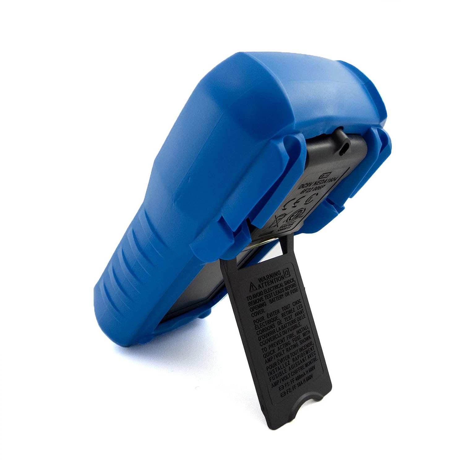
Figure 4: Visual representation of common domestic and electronics applications for the C-LOGIC 5100 Multimeter.
The C-LOGIC 5100 Digital Multimeter is suitable for a wide range of applications, including:
- Domestic Electrical Testing: Checking household wiring, outlets, batteries, and appliance continuity.
- Automotive Diagnostics: Testing vehicle electrical systems, battery voltage, and component resistance.
- Electronics Troubleshooting: Measuring voltage, current, resistance, and capacitance in electronic circuits, testing diodes and transistors.
- HVAC System Checks: Verifying voltage and current in heating, ventilation, and air conditioning systems.
- Hobbyist and DIY Projects: Essential tool for various electrical and electronic projects.
11. Warranty and Support
For information regarding warranty coverage, technical support, or customer service, please visit the official C-LOGIC website or contact their support team directly. You can find more product details at clogic-intl.com/clogic-5100 or the main website at clogic-intl.com.


