
1. Product Overview
The Hantek DSO2C10 is a 2-channel digital storage oscilloscope designed for precise electronic measurements. It features a 100 MHz analog channel bandwidth and a real-time sampling rate of 1 GSa/s, making it suitable for a wide range of applications from hobbyist projects to professional diagnostics.
Key features include:
- 2 independent channels with 100 MHz bandwidth.
- 1 GSa/s real-time sampling rate.
- 8M memory depth for waveform storage.
- Vertical range of 2mV/div to 10V/div with 8-bit resolution.
- Multiple trigger types: Edge, Pulse Width, Video, Slope, Overtime, Window, Pattern, Interval, Delay, UART, LIN, CAN, SPI, IIC.
- CAN decoding and protocol analysis for RS232/UART, I2C, SPI, CAN, LIN.
- Ability to save data in various formats: settings, waveform, reference waveform, CSV, image.
- 5-bit digital voltmeter and 6-bit hardware frequency indicator.
- 32 types of automatic measurements with real-time statistics (max, min, standard deviation, etc.).
- Dual channel DVM functions.
- Support for threshold testing and free measurements on screen.
- Abundant SCPI remote control commands.
- USB host/device external interfaces.

Figure 1.1: Front view of the Hantek DSO2C10 Digital Oscilloscope.
2. Components and Controls
This section details the physical components and controls of your Hantek DSO2C10 oscilloscope.
2.1 Front Panel

Figure 2.1: Detailed front view of the Hantek DSO2C10, showing the LCD display, control buttons, and input signals.
The front panel includes the main LCD display, various function buttons (e.g., MENU, AUTO SET, ACQUIRE, DISPLAY, SAVE/RECALL), rotary encoders for vertical (VOLTS/DIV, POSITION) and horizontal (SEC/DIV, HORIZ POSITION) adjustments, and input connectors for channels CH1 and CH2, along with an external trigger input.
2.2 Rear Panel
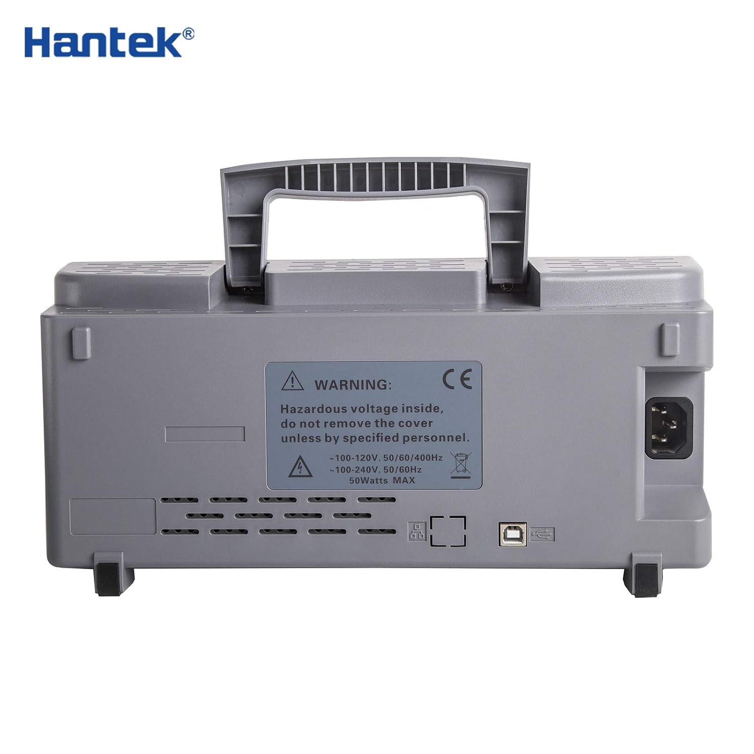
Figure 2.2: Rear view of the Hantek DSO2C10, highlighting the power input, USB ports, and ventilation.
The rear panel houses the main power input, USB host/device ports for data transfer and peripheral connection, and ventilation grilles. A warning label indicates hazardous voltage inside and advises against removing the cover.
2.3 Side Panels
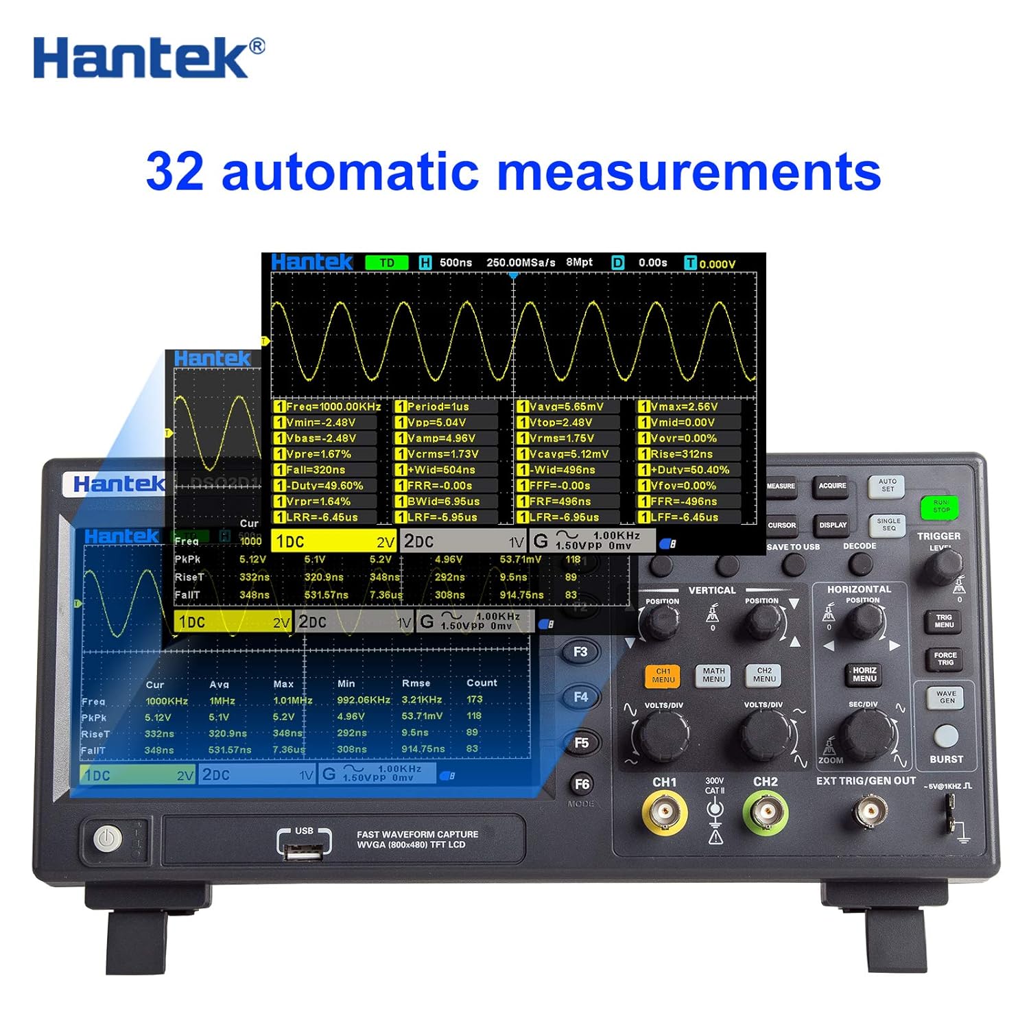

Figure 2.3: Side views of the Hantek DSO2C10, showing the compact design and additional ventilation.
The side panels feature additional ventilation for heat dissipation and contribute to the device's portable design, including a carrying handle for easy transport.
3. Setup Guide
Follow these steps to set up your Hantek DSO2C10 oscilloscope for initial use.
- Unpacking: Carefully remove the oscilloscope and all accessories from the packaging. Verify that all components listed in the "What's in the Box" section are present.
- Power Connection: Connect the provided power cable to the power input on the rear panel of the oscilloscope. Plug the other end into a suitable AC power outlet (100-240V, 50/60Hz).
- Probe Connection: Connect the oscilloscope probes to the CH1 and CH2 input BNC connectors on the front panel. Ensure a secure connection.
- Probe Compensation: Before taking measurements, it is crucial to compensate the probes.
- Connect the probe tip to the probe compensation output (usually a square wave test signal output on the front panel).
- Connect the probe ground clip to the ground terminal.
- Adjust the probe compensation screw on the probe until a flat-top square wave is displayed on the screen. Refer to the operating section for detailed instructions on adjusting vertical and horizontal scales.
- Power On: Press the power button, typically located on the front or side panel, to turn on the oscilloscope.
4. Operating Instructions
This section provides guidance on operating your Hantek DSO2C10 oscilloscope for various measurement tasks.
4.1 Basic Operation
- Vertical Controls (VOLTS/DIV): Use the VOLTS/DIV knobs for CH1 and CH2 to adjust the vertical scale (voltage per division) for each channel independently. The POSITION knobs adjust the vertical position of the waveform.
- Horizontal Controls (SEC/DIV): Use the SEC/DIV knob to adjust the horizontal scale (time per division). The HORIZ POSITION knob adjusts the horizontal position of the waveform.
- Trigger System: The trigger system stabilizes repetitive waveforms.
- Trigger Level: Adjust the TRIGGER LEVEL knob to set the voltage level at which the oscilloscope triggers.
- Trigger Mode: Select trigger modes (Edge, Pulse, Video, etc.) using the dedicated buttons or menu options.
- Trigger Source: Choose the trigger source (CH1, CH2, EXT, AC Line) from the trigger menu.
- Auto Set: Press the "AUTO SET" button for automatic waveform display optimization. This function automatically adjusts vertical, horizontal, and trigger settings to display a stable waveform.
4.2 Advanced Measurement Functions
The DSO2C10 offers 32 types of automatic measurements and advanced analysis capabilities.
The oscilloscope can display various parameters such as Frequency, Period, Max, Min, Peak-to-Peak, RMS, Duty Cycle, etc. These measurements can be accessed through the dedicated measurement menu, and the device provides real-time statistics for these values.
- Waveform Storage: Use the "SAVE/RECALL" function to save and recall waveforms, settings, and screenshots to internal memory or a connected USB drive.
- Protocol Analysis: The oscilloscope supports decoding and analysis for various serial protocols including RS232/UART, I2C, SPI, CAN, and LIN. Refer to the dedicated protocol analysis menu for configuration and display options.
- FFT Function: The Fast Fourier Transform (FFT) function allows for frequency domain analysis of waveforms. Access this feature through the Math menu.
- DVM Function: Utilize the integrated 5-bit digital voltmeter and 6-bit hardware frequency indicator for precise voltage and frequency readings.
5. Maintenance
Proper maintenance ensures the longevity and accuracy of your oscilloscope.
- Cleaning:
- Clean the exterior of the oscilloscope with a soft, damp cloth. Do not use abrasive cleaners or solvents.
- Ensure the screen is clean for optimal viewing. Use a soft, lint-free cloth specifically designed for electronic displays.
- Storage:
- Store the oscilloscope in a dry, dust-free environment when not in use.
- Avoid extreme temperatures and humidity.
- Probe Care:
- Handle probes carefully. Do not bend or stress the cables excessively.
- Regularly check probe tips and connectors for damage or wear.
- Firmware Updates: Periodically check the Hantek official website for firmware updates. Follow the provided instructions carefully for any update procedures.
Warning: Hazardous voltage inside. Do not remove the cover unless by specified personnel.
6. Troubleshooting
This section addresses common issues you might encounter with your Hantek DSO2C10 oscilloscope.
| Problem | Possible Cause | Solution |
|---|---|---|
| No display after power on. | Power cable not connected or faulty. Device not powered on. | Check power cable connection. Ensure power button is pressed. Verify power outlet functionality. |
| No waveform displayed. | Probe not connected or faulty. Input signal too small or too large. Incorrect vertical/horizontal settings. Trigger not set correctly. | Check probe connection. Adjust VOLTS/DIV and SEC/DIV settings. Use "AUTO SET". Adjust trigger level and mode. Ensure signal source is active. |
| Unstable waveform. | Trigger level incorrect. Trigger mode unsuitable for signal. Noise interference. | Adjust trigger level. Change trigger mode (e.g., to Edge for repetitive signals). Ensure proper grounding and minimize external noise. |
| Incorrect voltage readings. | Probe attenuation setting incorrect. Probe not compensated. | Verify probe attenuation setting (1X, 10X, 100X, 1000X) matches oscilloscope setting. Perform probe compensation. |
| USB data transfer issues. | Faulty USB cable. Incorrect USB mode. Driver issues on PC. | Try a different USB cable. Ensure oscilloscope is in the correct USB device mode. Install necessary drivers on your computer. |
7. Specifications
Detailed technical specifications for the Hantek DSO2C10 Digital Oscilloscope.
| Feature | Specification |
|---|---|
| Model | DSO2C10 |
| Channels | 2CH |
| Bandwidth | 100 MHz |
| Sample Rate | 1 GSa/s (single channel), 500 MSa/s (two channels) |
| Memory Depth | 8M |
| Vertical Range | 2mV/div ~ 10V/div |
| Vertical Resolution | 8 bits (up to 12 bits with high resolution mode) |
| Input Coupling | DC, AC, GND |
| Input Impedance | 1MΩ ± 2% || 20pF ± 3pF |
| Probe Attenuation Factors | 1X, 10X, 100X, 1000X |
| Max Input Voltage | 300V RMS (10X) |
| Trigger Types | Edge, Pulse Width, Video, Slope, Overtime, Window, Pattern, Interval, Delay, UART, LIN, CAN, SPI, IIC |
| Decoding & Protocol Analysis | RS232/UART, I2C, SPI, CAN, LIN |
| Automatic Measurements | 32 types with statistics |
| Digital Voltmeter | 5-bit |
| Hardware Frequency Indicator | 6-bit |
| Display Type | 7" TFT LCD |
| Interfaces | USB Host/Device |
| Power Source | Electric Cable (100-240V, 50/60Hz) |
| Dimensions (L x W x H) | 318 x 140 x 150 mm (approx.) |
| Safety Rating | CAT II |

Figure 7.1: Model comparison table for Hantek DSO2000 series oscilloscopes. Note that the DSO2C10 model does not include a built-in signal source (AFG).
8. What's in the Box
The Hantek DSO2C10 package typically includes the following items:
- 1 x Hantek DSO2C10 Digital Oscilloscope
- 1 x USB Data Cable
- 1 x Power Cable
- 1 x Probe (Note: Some packages may include two probes, verify upon receipt)
- 1 x Clip Line (Ground clip for probe)
9. Support and Warranty
For technical support, warranty information, or service inquiries, please refer to the official Hantek website or contact your local distributor. Keep your purchase receipt for warranty claims.
Product origin: China.