
1. Introduction
This manual provides essential information for the safe and efficient operation of your Zunate JLS-E-2S Variable Frequency Drive (VFD). Please read this manual thoroughly before installation, operation, or maintenance to ensure proper usage and prevent damage or injury. Keep this manual for future reference.
Safety Warnings
WARNING: Risk of electrical shock. Read the user manual carefully before operation. Wait at least 10 minutes after removing power before servicing to allow capacitors to discharge. Only qualified personnel should install, operate, and maintain this device.

Image 1: Top view of the Zunate JLS-E-2S VFD, showing the control panel and a prominent safety warning label. The label advises users to read the manual and wait 10 minutes after power removal before servicing due to electrical shock risk.
2. Product Features
- Constructed from high-quality ABS material, ensuring durability and a long service life.
- Features V/F closed-loop control for precise and stable operation.
- Incorporates PAM (Pulse Amplitude Modulation) output voltage regulation mode for enhanced control and stable performance.
- Offers rapid start and stop response times, contributing to efficient application performance.
- Designed with strong anti-interference capabilities, providing stable and reliable performance in industrial environments.
- Primarily suitable for industrial assembly line conveyor belts and similar applications.

Image 2: Angled view of the VFD with its terminal cover open, revealing the internal wiring block. This highlights the robust construction and accessibility for wiring.
3. Specifications
| Parameter | Value |
|---|---|
| Model | JLS-E-2S |
| Material | ABS |
| Input Voltage | Single-phase 220V |
| Output Voltage | Single-phase 220V |
| Control Method | V/F Closed Loop Control |
| Output Voltage Regulation Method | PAM Control |
| Power Options | 0.4KW (2.5A), 0.75KW (5A), 1.5KW (7A), 2.2KW (10A) |
| Main Application | Industrial assembly line conveyor belts |
| Manufacturer Reference | Zunatedzugr18mwo7456-12 |
| Serial Number (Example) | JLS0004E21G21030129 |

Image 3: Bottom view of the VFD, illustrating its compact design and potential mounting points.
4. Setup and Installation
Proper installation is crucial for the safe and reliable operation of the VFD. Ensure all power is disconnected before beginning any wiring procedures.
4.1 Mounting
- Mount the VFD in a well-ventilated area, away from direct sunlight, excessive dust, moisture, and corrosive gases.
- Ensure sufficient clearance around the unit for proper heat dissipation.
- Use appropriate fasteners to secure the VFD firmly to a stable surface.
4.2 Wiring Connections
Refer to the wiring diagrams and terminal labels on the unit for correct connections. The VFD supports single-phase 220V input and output.
- Input Power (L1, L2): Connect the single-phase 220V AC power supply to the L1 and L2 terminals.
- Motor Output (U, V, W): Connect the motor phases to the U, V, and W terminals.
- Ground (GND): Ensure the VFD is properly grounded to prevent electrical hazards.
- Control Terminals: Utilize the control terminals (e.g., X1, X2, X3, X4 for digital inputs; AO, YO for analog/digital outputs) for external control signals as required by your application.

Image 4: Detailed view of the VFD's terminal block, clearly showing labels for power input (L1, L2), motor output (U, V, W), and various control signal connections.
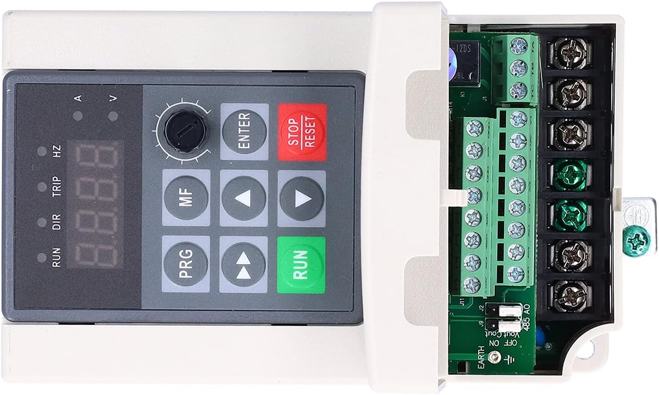
Image 5: Top-down perspective of the VFD with the terminal cover removed, providing a comprehensive view of all wiring points for power and control.
5. Operating Instructions
The VFD features an intuitive control panel for easy operation and parameter adjustment.
5.1 Control Panel Overview

Image 6: Close-up of the VFD's control panel, highlighting the digital display, rotary knob, and various function buttons.
- RUN Button (Green): Initiates motor operation.
- STOP/RESET Button (Red): Stops motor operation and resets fault conditions.
- PRG Button: Enters/exits parameter setting mode.
- ENTER Button: Confirms parameter selections or values.
- MF Button: Function button (specific function may vary based on programming).
- Up/Down Arrows: Navigate through menus or adjust parameter values.
- Rotary Knob: Used for fine-tuning frequency or parameter values.
- Digital Display: Shows operating status, frequency, voltage, current, and parameter values.

Image 7: Angled close-up of the control panel, providing a clear view of the buttons and rotary knob for user interaction.
5.2 Basic Operation
- Power On: Apply single-phase 220V power to the VFD. The display will illuminate.
- Set Frequency: Use the rotary knob or arrow buttons to set the desired output frequency.
- Start Motor: Press the RUN button to start the motor. The display will show the operating frequency.
- Stop Motor: Press the STOP/RESET button to stop the motor.
- Parameter Adjustment: Press the PRG button to enter parameter setting mode. Use arrow keys to navigate, ENTER to select, and the rotary knob/arrows to adjust values. Press PRG again to exit.
6. Maintenance
Regular maintenance helps ensure the longevity and optimal performance of your VFD.
- Cleaning: Periodically clean the exterior of the VFD with a soft, dry cloth. Ensure ventilation openings are free from dust and debris. Always disconnect power before cleaning.
- Inspection: Regularly inspect wiring connections for tightness and signs of wear or damage. Check for any unusual noises or odors during operation.
- Environment: Maintain the operating environment within specified temperature and humidity ranges.
7. Troubleshooting
This section provides general guidance for common issues. For complex problems, contact technical support.
- VFD Not Powering On: Check the input power supply and ensure all connections are secure. Verify the circuit breaker or fuse.
- Motor Not Running: Check if the RUN command is active. Verify motor wiring and ensure no fault codes are displayed on the VFD. Check motor parameters.
- Overcurrent/Overvoltage Fault: This could indicate an issue with the motor, load, or power supply. Consult the full manual for specific fault codes and remedies.
- Unusual Noise: Investigate the source of the noise. It could be from the motor, VFD, or mechanical components.
8. Warranty and Support
Specific warranty details are not provided in the product information. For warranty claims, technical support, or service, please contact your retailer or the manufacturer, Zunate, directly. Ensure you have your model number (JLS-E-2S) and serial number (e.g., JLS0004E21G21030129) available when contacting support.