
1. Product Overview
The ACEIRMC DC 6-30V Programmable Timer Relay Module is a versatile control unit designed for various applications requiring precise timing and relay switching. It features an LCD display for easy parameter setting and supports power input via DC 6-30V or Micro USB 5V. This module is suitable for smart home systems, industrial control, automatic irrigation, and other equipment requiring timed operations.

Figure 1: Top and bottom view of the ACEIRMC DC 6-30V Programmable Timer Relay Module.
Key Features:
- Programmable Delay Modes: Offers multiple timing modes for flexible control.
- Wide Operating Voltage: Supports DC 6V-30V and Micro USB 5V power supply.
- High Level Trigger: Compatible with 3V-24V trigger signals.
- High Output Capacity: Controls loads up to DC 30V/10A or AC 250V/10A.
- Adjustable Timing Range: From 0.1 seconds to 999 minutes.
- Reverse Polarity Protection: Built-in diode for circuit safety.
- Automatic Display Turn-off: LCD display turns off after 5 minutes of inactivity to save power.
- Parameter Memory: All settings are permanently saved after configuration.
2. Specifications
| Parameter | Value |
|---|---|
| Operating Voltage | DC 6V-30V (supports Micro USB 5V) |
| Output Capacity | DC 30V 10A, AC 250V 10A (Normally Open) |
| Quiescent Current | 20mA |
| Operating Current | 50mA |
| Operating Temperature | -40℃ to 85℃ |
| Timing Range | 0.1 seconds to 999 minutes (continuously adjustable) |
| Trigger Signal Source | High voltage level trigger (3.0V-24V) |
| Optocoupler Isolation | Yes, for improved anti-interference ability |
| Relay Contact Type | Passive, Normally Open (NO) |
| Dimensions | 0.25 x 0.25 x 0.25 cm |
| Weight | 50 g |
3. Setup and Wiring
Before connecting the module, ensure all power sources are disconnected. The module can be powered via the DC 6-30V terminals or a 5V Micro USB port. The trigger signal source requires a high voltage level between 3.0V and 24V. For enhanced anti-interference, the signal ground and system ground can be kept separate or connected as needed.
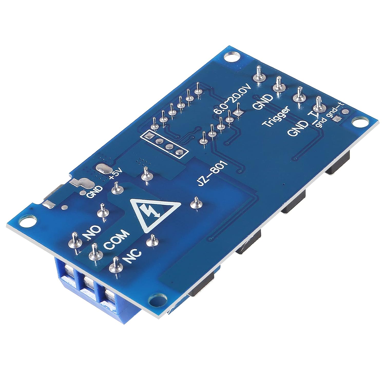
Figure 2: Bottom view showing power input (6.0-20.0V, GND), trigger input (Trigger, GND_T), and relay output (NO, COM, NC).
Wiring Connections:
- Power Input: Connect DC 6-30V to the designated terminals (6.0-20.0V and GND) or use a 5V Micro USB cable.
- Trigger Input: Connect the trigger signal (3.0V-24V) to the 'Trigger' terminal and its ground to 'GND_T'.
- Relay Output: The relay has Normally Open (NO), Common (COM), and Normally Closed (NC) contacts. Connect your load to COM and either NO (for normally open operation) or NC (for normally closed operation). The relay contact is passive, meaning it acts as a switch and does not provide power to the load directly.
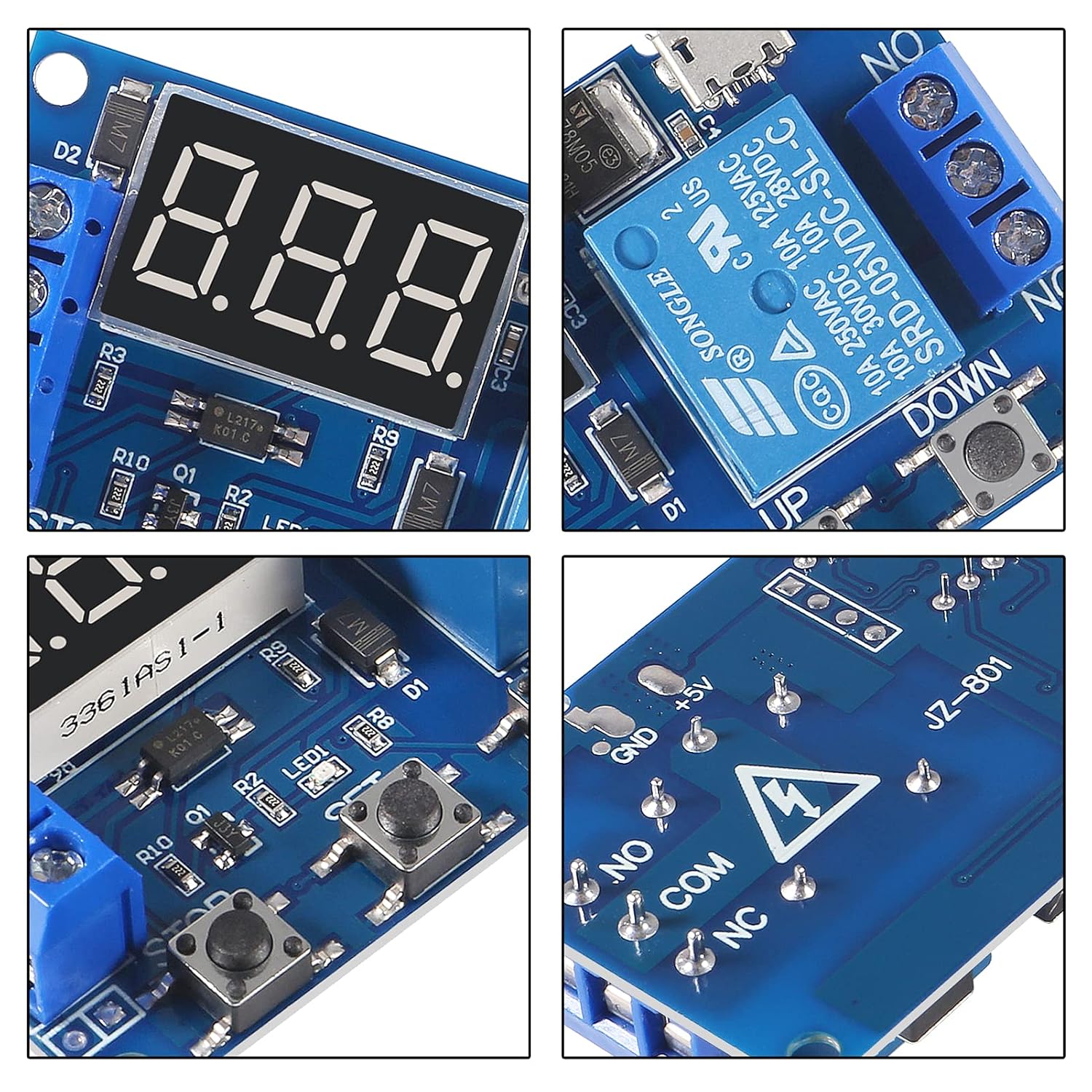
Figure 3: Close-up of the module's LCD display and control buttons (STOP, SET, UP, DOWN).
4. Operation Modes and Parameter Setting
The module offers several programmable operation modes. Parameters (OP, CL, LOP) can be set individually and are saved permanently. Press the 'SET' button to enter parameter setting mode.
Parameter Definitions:
- OP: Conduction time (relay connected).
- CL: Disconnection time (relay disconnected).
- LOP: Loop times (1-999, "---" indicates infinite loops).
Operation Modes:
- P1 Mode: After receiving a trigger signal, the relay connects for the 'OP' time, then disconnects.
- P1.1: If triggered again during 'OP' time, the signal is ignored.
- P1.2: If triggered again during 'OP' time, the timing restarts.
- P1.3: If triggered again during 'OP' time, the relay disconnects, and timing stops.
- P-2 Mode: After receiving a trigger signal, the relay disconnects for 'CL' time, then connects for 'OP' time, and finally disconnects.
- P3.1 Mode: After receiving a trigger signal, the relay connects for 'OP' time, then disconnects for 'CL' time, and this cycle repeats for 'LOP' times. If triggered during the loop, the relay disconnects, and timing stops.
- P3.2 Mode: After power-on (no trigger needed), the relay connects for 'OP' time, then disconnects for 'CL' time, and this cycle repeats for 'LOP' times.
- P-4 Mode (Signal Holding): If a trigger signal is present, the timing resets, and the relay remains connected. When the signal disappears, the relay disconnects after 'OP' time. If a signal reappears during timing, the timing resets.
Setting Parameters:
- Press the 'SET' button to enter parameter setting mode. The display will show the current mode (e.g., P1.1).
- Use 'UP' and 'DOWN' buttons to select the desired operation mode.
- Press 'SET' again to enter the parameter adjustment for the selected mode. The first parameter (e.g., OP) will flash.
- Use 'UP' and 'DOWN' to adjust the value. A short press changes by 0.1/1/10 units, a long press changes rapidly.
- Press 'STOP' to switch between time units (seconds, minutes, hours). The decimal point indicates the unit: no decimal point for seconds (1-999s), one decimal point for 0.1-99.9s, two decimal points for 0.01-9.99s.
- Press 'SET' to move to the next parameter (CL, then LOP if applicable). Repeat steps 4 and 5.
- After setting all parameters for the mode, press 'SET' again to save and exit.
Sleep Mode (C-L):
If there is no operation for 5 minutes, the LCD display will automatically turn off to conserve power. Press any button to wake up the display.
5. Maintenance
The ACEIRMC Timer Relay Module is designed for durability. To ensure optimal performance and longevity:
- Operate within the specified voltage and temperature ranges.
- Avoid exposing the module to excessive moisture, dust, or corrosive environments.
- Ensure proper ventilation if used in an enclosed space.
- The built-in diode provides protection against accidental reverse polarity; however, always double-check wiring before applying power.
- Clean the module gently with a dry, soft cloth if necessary. Do not use harsh chemicals.
6. Troubleshooting
- Display is off: If the display is off, it might be in sleep mode. Press any button (STOP, SET, UP, DOWN) to reactivate the display. Ensure the module is receiving power (6-30V DC or 5V Micro USB).
- Module not responding to trigger: Verify the trigger signal voltage is within the 3.0V-24V range. Check wiring connections for the trigger input. Ensure the selected operation mode (P1, P2, P3.1, P4) is appropriate for your trigger logic.
- Relay not switching: Check the load connections to the NO/COM/NC terminals. Ensure the load current and voltage do not exceed the relay's maximum capacity (DC 30V/10A, AC 250V/10A). Review the set 'OP' and 'CL' times to ensure they are configured as intended.
- Parameters not saving: All parameters are designed to be permanently saved after setting. Ensure you press 'SET' to confirm and exit the parameter adjustment mode after making changes.
- Incorrect timing: Double-check the 'OP', 'CL', and 'LOP' values and their corresponding time units (seconds, minutes, hours) indicated by the decimal point on the display.
7. Warranty and Support
For warranty information, technical support, or any inquiries regarding the ACEIRMC DC 6-30V Programmable Timer Relay Module, please contact your retailer or the manufacturer directly. Keep your purchase receipt for any warranty claims.