1. Introduction
1.1 Product Overview
This manual provides essential information for the proper handling, installation, and understanding of the Davitu 42LH50YD-CA Motherboard LC91B EAX60737402(0) Printed Circuit Board (PCB). This PCB is primarily intended for data recovery and repair issues related to Hard Disk Drives (HDDs).
1.2 Important Notice
Please read the following points carefully before proceeding:
- This product is a Printed Circuit Board (PCB) only, not a complete Hard Drive.
- The PCB board number is printed directly on the board, not on any sticker. Verify this number for compatibility.
- These boards are USED and have been tested to be in good working condition before shipping. Components are intact, and interfaces are undamaged.
- For successful data recovery, BIOS CHIP SWAPPING IS A MUST. The unique BIOS (ROM or NVRAM chip) on most HDD boards contains data critical for accessing the HDD system area. Incompatible BIOS information will prevent data access.
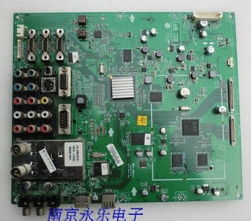
Figure 1: Davitu 42LH50YD-CA Motherboard LC91B EAX60737402(0) PCB. This image displays the Davitu 42LH50YD-CA Motherboard LC91B EAX60737402(0) Printed Circuit Board (PCB). The board is green and features various electronic components, connectors, and integrated circuits. Key features visible include multiple input/output ports (such as RCA, VGA, and USB), a heatsink over a central processing unit, and various capacitors and resistors. The overall layout is typical of a main logic board for electronic devices, designed for specific data processing and connectivity functions.
2. Setup and Installation
2.1 Pre-Installation Checks
- Ensure the replacement PCB's board number matches your original HDD's PCB.
- Confirm that the original HDD's issue is indeed related to the PCB and not internal mechanical damage.
- Gather necessary tools, including a soldering iron, solder, flux, and appropriate screwdrivers for delicate electronic work.
2.2 BIOS Chip Swapping Procedure
This is the most critical step for data recovery. The BIOS chip from your original, faulty PCB must be carefully desoldered and transferred to the new (replacement) PCB. This ensures that the unique drive-specific information is retained, allowing the HDD to be recognized and accessed.
- Identify the BIOS (ROM or NVRAM) chip on both the original and the replacement PCBs. This chip is typically an 8-pin SOP (Small Outline Package) IC.
- Carefully desolder the BIOS chip from the original PCB using appropriate desoldering techniques (e.g., hot air station or fine-tip soldering iron with desoldering braid). Exercise extreme caution to avoid damaging the chip or surrounding components.
- Clean the pads on the replacement PCB where the BIOS chip will be installed.
- Carefully solder the original BIOS chip onto the designated pads of the replacement PCB, ensuring correct orientation (pin 1 alignment).
Warning: This procedure requires advanced soldering skills and specialized equipment. Incorrect execution can permanently damage the BIOS chip or the PCB, rendering data recovery impossible. If you are not confident, seek professional data recovery services.
2.3 Physical Installation
Once the BIOS chip has been successfully swapped, the replacement PCB can be attached to the HDD body. Ensure all screws are tightened securely and connections are firm.
3. Operation
After successful PCB replacement and BIOS chip transfer, the HDD should now be able to power on and be recognized by a computer system. The "operation" of this PCB is integrated with the HDD's functionality for data access.
3.1 Data Recovery Process
Connect the repaired HDD to a computer using appropriate SATA/IDE to USB adapters or directly to a motherboard's port. Use data recovery software or operating system tools to attempt to access and retrieve data from the drive. The success of data recovery depends on the original extent of damage to the HDD and the precision of the PCB replacement.
4. Maintenance
4.1 Handling and Storage
- Always handle the PCB by its edges to avoid touching components or traces, which can cause electrostatic discharge (ESD) damage.
- Store the PCB in an anti-static bag when not in use.
- Keep the PCB in a dry, cool environment, away from direct sunlight and extreme temperatures.
4.2 Cleaning
If cleaning is necessary, use a soft, lint-free cloth and isopropyl alcohol. Avoid using harsh chemicals or abrasive materials. Ensure the PCB is completely dry before re-installation or use.
5. Troubleshooting
5.1 Common Issues and Solutions
- HDD not recognized after PCB swap:
- Verify that the BIOS chip from the original PCB was correctly transferred and soldered to the new PCB. This is the most common cause of failure.
- Check all connections between the PCB and the HDD.
- Ensure the replacement PCB's board number is an exact match.
- Clicking or unusual noises from HDD:
- This usually indicates a mechanical issue with the HDD itself, not the PCB. PCB replacement will not resolve mechanical failures.
- Discontinue power immediately to prevent further damage.
- No power to HDD:
- Check power supply connections.
- Ensure the PCB is correctly seated and all screws are tightened.
5.2 Diagnostic Steps
If issues persist, consider the following:
- Re-examine the soldering points of the BIOS chip under magnification for cold joints or bridges.
- Test the HDD with its original PCB (if it still powers on, even if not recognized) to confirm the issue is indeed PCB-related.
- Consult with a professional data recovery specialist if you are unable to resolve the issue.
6. Specifications
| Attribute | Detail |
|---|---|
| Product Type | Printed Circuit Board (PCB) for HDD |
| Model Number | DVT-91B1C49EB40D5372B697F87C22ABE62E |
| Compatible Motherboard | 42LH50YD-CA Motherboard LC91B EAX60737402(0) |
| Brand | DAVITU |
| Condition | Used, Tested Good Working Condition |
| Use Case | Data Recovery / Repair Issues |
| Communication | Wire Control |
| Origin | JP (Japan) |
| Material Type | Other |
7. Warranty Information
As this product is a used component intended for specialized repair and data recovery, specific manufacturer warranties may not apply. The seller confirms that the PCB has been tested and is in good working condition prior to shipping. Any issues arising from improper installation, BIOS chip transfer, or pre-existing damage to the HDD are not covered.
For details regarding return policies, please refer to the purchase platform's terms and conditions.
8. Technical Support
Given the specialized nature of this product and the technical skills required for its application (especially BIOS chip swapping), direct technical support from the manufacturer or seller for installation procedures may be limited.
If you encounter difficulties or are not confident in performing the necessary procedures, it is highly recommended to:
- Consult online forums and communities dedicated to HDD repair and data recovery.
- Seek assistance from a qualified data recovery professional.
For inquiries related to the product's condition upon arrival or discrepancies with the listing, please contact your seller through the platform where the purchase was made.


