1. Introduction
This manual provides detailed instructions for the Youmile DC 12-24V 5-Axis Mach3 CNC Breakout Board Interface Card. This board is designed to facilitate communication between a computer running Mach3 software and stepper motor drivers, enabling precise control for CNC applications. It features optical isolation for enhanced safety and signal integrity.

Image 1.1: The Youmile 5-Axis Mach3 CNC Breakout Board, shown with the included USB cable, parallel port cable, and XH2.54 4P cables.
2. Product Features
- Mach3 Compatibility: Fully supports Mach3 and other parallel port control software.
- Isolated Power Supply: Separate USB and peripheral power supplies (12-24V DC) ensure computer safety.
- Optical Isolation: All input signals are optically isolated, allowing connection to emergency stops, tool setting, and limit switches.
- 5-Axis Control: Supports control of up to 5 stepper motor axes via optocoupler drivers.
- Spindle Control:
- Unidirectional relay output (P17) for spindle switch control.
- Isolated 0-10V analog voltage output (P1) for controlling inverters with corresponding analog interfaces for spindle speed.
- PWM output (P1) for controlling spindle regulators with optocoupler input.
- Wide Voltage Input: Peripheral power input supports 12-24V DC with anti-reverse connection function.
- Driver Compatibility: Can connect to common cathode/anode drivers with a 5V input level.
3. Package Contents
Verify that all items listed below are present in your package:
- 1 x Youmile 5-Axis Mach3 CNC Breakout Board Interface Card
- 1 x USB Cable
- 1 x Parallel Port Cable
- 5 x XH2.54 4P Cables

Image 3.1: The USB cable and parallel port cable included with the breakout board.
4. Setup Instructions
Follow these steps to set up your Youmile CNC Breakout Board:
- Power Supply Connection: Connect a 12-24V DC power supply to the designated terminal block on the board. Ensure correct polarity, as the board includes anti-reverse connection protection.
- USB Connection: Connect the provided USB cable from the breakout board to your computer. This provides power isolation for the computer.
- Parallel Port Connection: Connect the provided parallel port cable from the breakout board to the parallel port on your computer. This is the primary data interface for Mach3 control.
- Stepper Motor Driver Connection: Connect your stepper motor drivers to the appropriate output pins (PUL, DIR, ENA for each axis) on the breakout board using the XH2.54 4P cables. The board supports up to 5 axes. Refer to the wiring diagram for specific pin assignments.
- Emergency Stop and Limit Switches: Connect emergency stop buttons, tool setting probes, and limit switches to the optically isolated input signals. These inputs are crucial for safe operation.
- Spindle Control (Optional):
- For spindle ON/OFF control, connect your spindle relay to port P17.
- For variable spindle speed control, connect your inverter's analog input to the 0-10V output on port P1, or connect your spindle regulator's PWM input to the PWM output on port P1.
- Software Configuration: Install and configure Mach3 software on your computer. Ensure the parallel port settings within Mach3 match the physical connections and pin assignments of the breakout board.
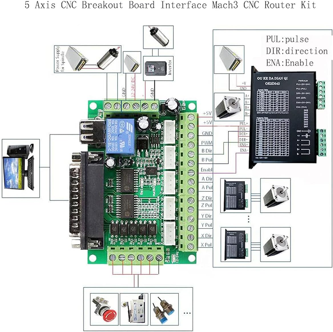
Image 4.1: A system diagram illustrating the typical connections for the 5-Axis CNC Breakout Board, including power, computer, and stepper motor drivers.
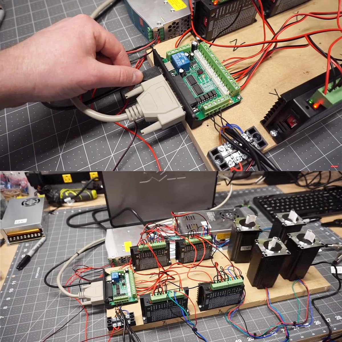
Image 4.2: An example of the breakout board integrated into a functional CNC control system with multiple stepper motor drivers.
5. Operating Instructions
Once the hardware is connected and Mach3 software is configured, you can begin operating your CNC machine:
- Power On: Ensure all connections are secure before powering on the 12-24V DC peripheral power supply and then your computer.
- Launch Mach3: Start the Mach3 software on your computer.
- Verify Connections: Within Mach3, verify that the breakout board is recognized and that all axes and inputs (e.g., limit switches, E-stop) are functioning correctly. Use the diagnostic screen in Mach3 for this purpose.
- Load G-Code: Load your desired G-code program into Mach3.
- Machine Operation: Follow Mach3's procedures for homing the machine, setting work offsets, and initiating the G-code program. Monitor machine movement and respond to any errors or unexpected behavior.
- Emergency Stop: Always be prepared to press the emergency stop button in case of any malfunction or unsafe condition.
6. Wiring Diagram and Pinout
The following diagram illustrates the pin assignments and connections for the Youmile 5-Axis Mach3 CNC Breakout Board. This is essential for correct wiring of stepper motor drivers, limit switches, and spindle control.

Image 6.1: Detailed pinout diagram of the Youmile 5-Axis Mach3 CNC Breakout Board, showing connections for power, inputs, outputs, and motor drivers.
Key Pin Assignments:
- P1: PWM Output / 0-10V Analog Output (Spindle Speed Control)
- P2-P9: Stepper Motor Pulse (PUL) and Direction (DIR) Signals for X, Y, Z, A, B axes.
- P10-P15: Input Signals (e.g., Stutter Stop, Tool Setting, X/Y/Z Spacing)
- P17: Relay Output (Spindle ON/OFF)
- GND: Ground Connections
- 12-24V Power Supply: Main power input for the board.
- USB: Power for optical isolation and communication.
7. Specifications
| Feature | Specification |
|---|---|
| Model Number | JK-YM-093 |
| Brand | Youmile |
| Input Voltage | DC 12-24V (Peripheral Power) |
| Axes Supported | 5-Axis |
| Interface | Parallel Port, USB |
| Compatibility | Mach3 and other parallel port control software |
| Isolation | Optical Coupler Isolation for all input signals |
| Spindle Control Output | P17 Relay Output, P1 0-10V Analog Output, P1 PWM Output |
| Compatible Devices | Personal Computer, Laptop |
| Operating System | Windows (as per Mach3 requirements) |
| UPC | 612840761371 |
8. Troubleshooting
If you encounter issues with your Youmile CNC Breakout Board, consider the following:
- No Power: Ensure the 12-24V DC power supply is correctly connected and providing power. Check the USB connection for computer power isolation.
- No Communication with Mach3:
- Verify the parallel port cable is securely connected at both ends.
- Check Mach3's port and pin settings to ensure they match your computer's parallel port configuration and the breakout board's pinout.
- Ensure Mach3 is properly installed and configured for parallel port control. Some users report better compatibility with Windows 7 (32-bit) for parallel port Mach3 setups.
- Motors Not Moving:
- Confirm stepper motor drivers are correctly wired to the breakout board and receiving power.
- Check Mach3's motor tuning settings for correct steps per unit, velocity, and acceleration.
- Verify that the Enable (ENA) signals for the motor drivers are active.
- Input Signals Not Responding (E-Stop, Limits):
- Ensure switches are correctly wired to the optically isolated input pins.
- Check Mach3's input signal configuration (active high/low, assigned pins).
- Spindle Control Issues:
- For relay control (P17), verify wiring and Mach3 output settings.
- For 0-10V or PWM control (P1), ensure the inverter/regulator is compatible and correctly wired, and Mach3's spindle settings are configured.
9. Safety Information
Always observe the following safety precautions when working with electronic components and CNC machinery:
- Electrical Safety: Ensure all power connections are made correctly and securely. Disconnect power before making or changing any wiring connections.
- Emergency Stop: Always have an easily accessible and functional emergency stop button. Test it regularly.
- Proper Grounding: Ensure all components of your CNC system are properly grounded to prevent electrical hazards.
- Read Manuals: Refer to the manuals for all connected components (stepper drivers, motors, spindle, Mach3 software) for their specific safety guidelines.
- Supervision: Never leave a running CNC machine unattended.
10. Warranty and Support
For warranty information and technical support, please refer to the product's purchase documentation or contact Youmile customer service directly. Keep your purchase receipt for warranty claims.
For additional resources and community support regarding Mach3 software and CNC applications, consider visiting relevant online forums and documentation.


