
1. Introduction
Thank you for choosing the SATMW 620A Digital Multimeter. This ultraportable, auto-ranging multi-tester is designed for accurate and reliable measurement of various electrical parameters. This manual provides essential information for safe and effective use of your device.
Key features of the SATMW 620A Digital Multimeter include:
- Measures AC/DC current, AC/DC voltage, resistance, diode, capacitance, temperature, and frequency.
- Non-Contact Voltage (NCV) detection and live/zero line detection with audible and visual alarms.
- Large 4.77-inch LCD display with backlight for clear readings.
- Auto-ranging and manual ranging modes for ease of use.
- Overload protection and durable silicone sheath for safety and longevity.
- Compact, palm-sized design for portability.
- Automatic power-off function to conserve battery life.
- Additional functions: data hold, flashlight, Celsius/Fahrenheit degree display.

Figure 1.1: Overview of the SATMW 620A Digital Multimeter's main features, including AC and DC voltage/current, resistance, diode, NCV, temperature, frequency, data retention, and silicone sheath.
2. Safety Information
To ensure safe operation and avoid damage to the meter, please read and follow all safety instructions carefully. Improper use can result in electric shock or damage to the instrument.
- Always ensure the test leads are properly connected and the function switch is set to the correct range before making any measurements.
- Do not exceed the maximum input values specified for each range.
- Exercise extreme caution when working with voltages above 30V AC RMS, 42V peak, or 60V DC. These voltages pose a shock hazard.
- Before measuring current, ensure the circuit is de-energized and the meter is connected in series with the load.
- Disconnect the test leads from the circuit before changing functions or ranges.
- Do not use the meter if it appears damaged or if the insulation on the test leads is compromised.
- Replace batteries immediately when the low battery indicator appears to ensure accurate readings.
- Do not operate the meter in explosive gas, vapor, or dusty environments.
- Always use appropriate personal protective equipment (PPE) when working with electrical circuits.
3. Product Overview
3.1 Components
The SATMW 620A Digital Multimeter features a robust design with a clear LCD display and intuitive controls. Familiarize yourself with the components shown below.
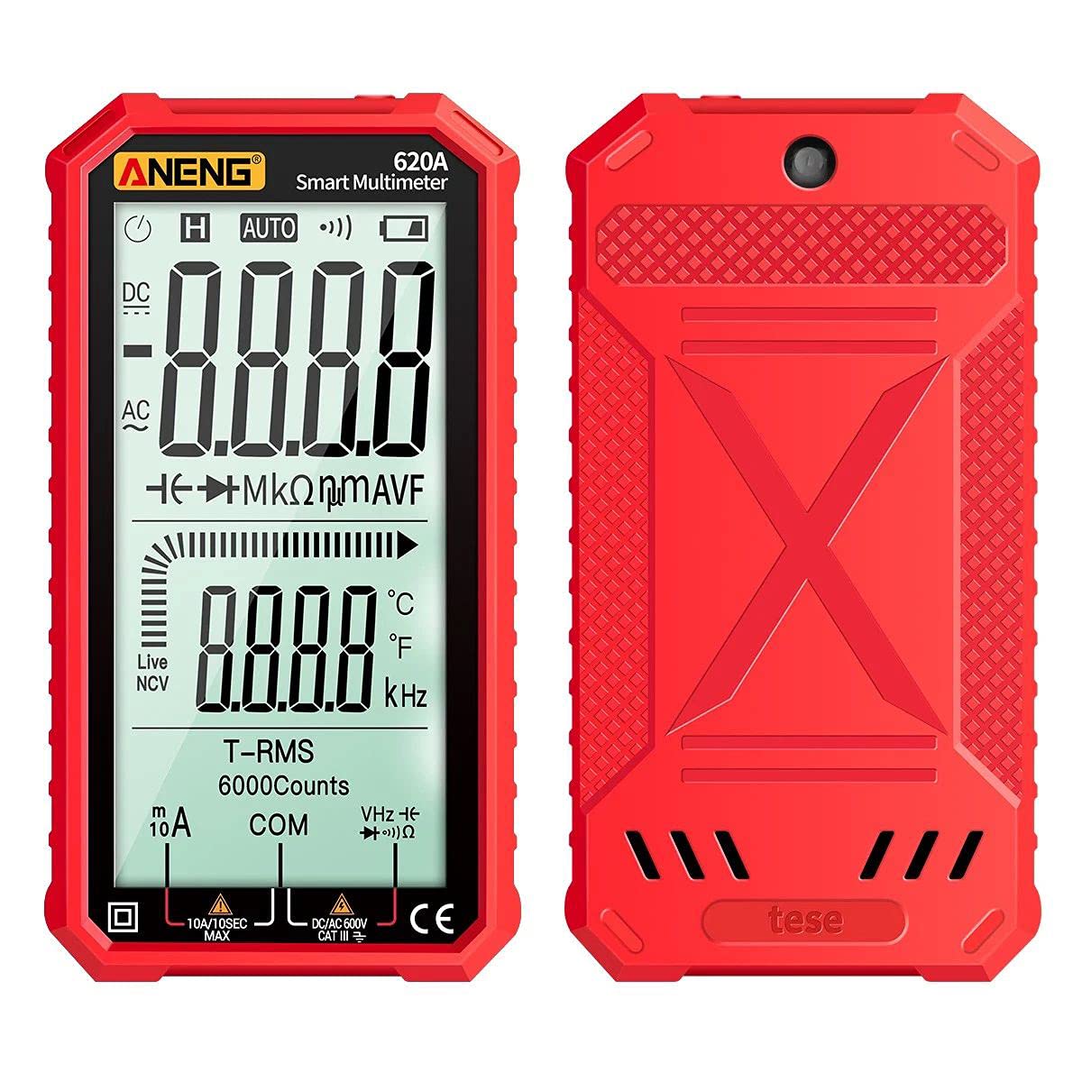
Figure 3.1: Front view of the SATMW 620A Digital Multimeter, showing the display, function buttons, and input jacks.

Figure 3.2: Exploded view illustrating the internal components of the multimeter, including the HD LCD digital display screen, circuit board, burn-proof fuse, test lead jacks, battery cover, and anti-drop silicone protective layer.
3.2 Dimensions
The compact design of the 620A makes it highly portable.

Figure 3.3: Physical dimensions of the SATMW 620A Digital Multimeter, measuring approximately 142.7mm (5.62in) in length, 77.4mm (3.04in) in width, and 23.8mm (0.93in) in thickness.
4. Setup
4.1 Battery Installation
The SATMW 620A Multimeter requires two AAA alkaline batteries (not included) for operation.
- Locate the battery compartment cover on the back of the multimeter.
- Use a screwdriver to loosen the screw(s) securing the cover.
- Remove the battery cover.
- Insert two AAA alkaline batteries, ensuring correct polarity (+ and -).
- Replace the battery cover and tighten the screw(s).
Note: Always replace both batteries at the same time. Remove batteries if the meter is not used for an extended period to prevent leakage.
5. Operating Instructions
5.1 Power On/Off
Press the power button to turn the multimeter on. The device will automatically power off after 15 minutes of inactivity to conserve battery life. Press the power button again to turn it off manually.
5.2 Auto-Ranging and Manual Ranging
The 620A features both auto-ranging and manual ranging modes. In auto-ranging mode, the meter automatically selects the appropriate measurement range. For specific applications, you can switch to manual ranging if desired (refer to the device's specific button for this function, usually labeled 'RANGE' or similar, though not explicitly detailed in provided data).
5.3 Function Selection
Rotate the central rotary switch to select the desired measurement function (e.g., Voltage, Current, Resistance, Diode, Capacitance, Temperature, Frequency, NCV).
5.4 Measuring AC/DC Voltage
- Set the rotary switch to the 'V' (Voltage) position. The meter will typically auto-detect AC or DC.
- Insert the red test lead into the 'VΩHz' jack and the black test lead into the 'COM' jack.
- Connect the test probes in parallel across the circuit or component to be measured.
- Read the voltage value on the display.
5.5 Measuring AC/DC Current
- Set the rotary switch to the 'A' (Current) position.
- For measurements up to 10A, insert the red test lead into the '10A' jack and the black test lead into the 'COM' jack.
- For measurements up to 6000mA, insert the red test lead into the 'mA' jack and the black test lead into the 'COM' jack.
- Caution: Ensure the circuit is de-energized before connecting the meter. Connect the test probes in series with the circuit to be measured.
- Re-energize the circuit and read the current value on the display.
5.6 Measuring Resistance
- Set the rotary switch to the 'Ω' (Resistance) position.
- Insert the red test lead into the 'VΩHz' jack and the black test lead into the 'COM' jack.
- Ensure the circuit or component is de-energized before connecting the test probes across it.
- Read the resistance value on the display.
5.7 Diode Test
- Set the rotary switch to the 'Diode' position (often shared with resistance or continuity).
- Insert the red test lead into the 'VΩHz' jack and the black test lead into the 'COM' jack.
- Connect the red probe to the anode and the black probe to the cathode of the diode.
- The display will show the forward voltage drop. Reverse the probes; an open circuit (OL) reading indicates a good diode.
5.8 Capacitance Measurement
- Set the rotary switch to the 'Capacitance' position (often labeled 'F' for Farad).
- Insert the red test lead into the 'VΩHz' jack and the black test lead into the 'COM' jack.
- Ensure the capacitor is fully discharged before connecting the test probes across it.
- Read the capacitance value on the display.
5.9 Temperature Measurement
- Set the rotary switch to the 'Temp' position (often labeled '°C/°F').
- Insert the temperature probe into the appropriate jacks (refer to the probe's markings and meter's jacks, typically 'VΩHz' and 'COM').
- Place the tip of the temperature probe on or near the object whose temperature is to be measured.
- Read the temperature value on the display. Use the 'SEL' button to switch between Celsius and Fahrenheit if available.
5.10 Frequency Measurement
- Set the rotary switch to the 'Hz' (Frequency) position.
- Insert the red test lead into the 'VΩHz' jack and the black test lead into the 'COM' jack.
- Connect the test probes across the circuit where frequency is to be measured.
- Read the frequency value on the display.
5.11 Non-Contact Voltage (NCV) Detection
- Set the rotary switch to the 'NCV' position.
- Move the top end of the multimeter near the conductor or outlet.
- If AC voltage is detected, the meter will emit an audible beep and the NCV indicator will light up. The intensity of the beeps and lights indicates the strength of the electric field.
5.12 Live/Zero Line Detection
This function helps identify live (firewire) and neutral (zero) lines in an AC circuit.
- Set the rotary switch to the 'Live' position (often shared with NCV or a dedicated button).
- Insert one test lead (typically the red one) into the 'VΩHz' jack.
- Touch the probe to the conductor or socket.
- If it's a live line, the display will turn red and the meter will beep rapidly. If it's a zero line, the display will remain normal (or show 'Live' without red background/rapid beep).

Figure 5.1: Illustration of zero line identification (left, no beep) and firewire recognition (right, screen turns red with rapid beep) using the multimeter's live line detection feature.
5.13 Data Hold Function
Press the 'HOLD' button to freeze the current reading on the display. Press it again to release the hold and resume live measurements.
5.14 Backlight and Flashlight
Long press the backlight button (often labeled 'H' or 'Light') to turn on the display backlight for improved visibility in dim conditions. A short press may activate a flashlight function if available.

Figure 5.2: The backlight button on the SATMW 620A Digital Multimeter, which activates the HD LCD screen display, measuring 4.77 inches (121.1mm).
5.15 Auto Power Off
The multimeter will automatically power off after approximately 15 minutes of inactivity to save battery power. To disable this feature temporarily (if supported, refer to specific device instructions) or to reactivate, cycle the power.
6. Maintenance
6.1 Cleaning
To clean the meter, wipe the case with a damp cloth and a mild detergent. Do not use abrasives or solvents. Ensure the meter is completely dry before use.
6.2 Battery Replacement
When the low battery indicator appears on the display, replace the batteries as described in Section 4.1. Always use two new AAA alkaline batteries.
7. Troubleshooting
If you encounter issues with your SATMW 620A Digital Multimeter, refer to the following common problems and solutions:
- No Display: Check if the batteries are correctly installed and have sufficient charge. Replace batteries if necessary. Ensure the power button is pressed.
- Incorrect Readings: Verify that the function switch is set to the correct measurement type and range. Ensure test leads are properly connected and not damaged. Check for proper circuit connection.
- 'OL' (Overload) Display: This indicates that the input value exceeds the selected range. Switch to a higher range or ensure the input is within the meter's capabilities.
- Buzzer Not Working (Continuity/NCV): Ensure the function is correctly selected. Check if the battery is low, as some functions may be affected by low power.
- Meter Does Not Turn On: Confirm battery installation and charge. If the issue persists, contact customer support.
8. Specifications
The following table details the technical specifications of the SATMW 620A Digital Multimeter:
| Parameter | Range | Resolution | Accuracy |
|---|---|---|---|
| AC Current | 6000mA 10A | 1mA 0.01A | (1.0% reading + 8 digits) |
| DC Current | 6000mA 10A | 1mA 0.01A | (1.0% reading + 5 digits) |
| DC Voltage | 6V 60V 600V | 0.001V 0.01V 0.1V | (0.5% reading + 3 digits) |
| AC Voltage | 6V 60V 600V | 0.001V 0.01V 0.1V | (0.8% reading + 5 digits) |
| Resistance | 600Ω 6kΩ 60kΩ 600kΩ 6MΩ 60MΩ | 0.1Ω 0.001kΩ 0.01kΩ 0.1kΩ 0.001MΩ 0.01MΩ | (0.8% reading + 3 digits) |
| Capacitance | 6nF 600nF 6µF 60µF 600µF 6mF 60mF | 0.001nF 0.1nF 0.001µF 0.01µF 0.1µF 1µF 0.01mF | (10% reading + 40 digits) (2.5% reading + 20 digits) (2.5% reading + 20 digits) (2.5% reading + 20 digits) (2.5% reading + 20 digits) (5% reading + 5 digits) (10% reading + 5 digits) |
| Temperature | -40 ~ 1000°C -40 ~ 1832°F | 1°C 1°F | (1% reading + 3) |
| Frequency (via gear A) | 100.0Hz 1000Hz | 0.1Hz 1Hz | (1.0% reading + 5 digits) |
| Frequency (via gear V) | 100.0Hz 1000Hz | 0.1Hz 1Hz | (1.0% reading + 5 digits) |
General Specifications:
- Brand: SATMW
- Material: ABS
- Max. Display Value: 6000 counts
- Automatic Shutdown Time: 15 minutes
- Maximum Operating Height: 2000 meters
- Battery Type: AAA alkaline battery (2pcs, NOT INCLUDED)
- Item Size: 14.27 x 7.74 x 2.38 cm / 5.61 x 3.04 x 0.93 inches
- Item Weight: 183.5 g / 6.47 oz
- Overload Protection: 600V DC/AC (for Continuity)
9. Warranty and Support
Specific warranty information for the SATMW 620A Digital Multimeter is not provided in this manual. For warranty details, technical support, or service inquiries, please refer to the product packaging, the seller's website, or contact the manufacturer directly.
