1. Introduction
This manual provides essential information for the installation, operation, and maintenance of the Cisco Catalyst 9500 C9500-24Y4C-A 24-Port Network Advantage Switch. Please read this manual thoroughly before using the device to ensure proper setup and functionality. This switch is designed for enterprise-level networking environments, offering high performance and advanced features.
2. Safety Information
WARNING: Failure to follow these safety instructions can result in injury or damage to the product.
- Ensure the power source matches the voltage requirements of the switch.
- Do not operate the switch in environments with excessive moisture or extreme temperatures. The upper temperature rating is 40 degrees Celsius.
- Always disconnect power before performing any maintenance or installation procedures.
- Proper grounding is essential for safe operation.
- Only qualified personnel should install and service this equipment.
3. Package Contents
Verify that your package contains the following items:
- Cisco Catalyst 9500 C9500-24Y4C-A Switch
- Power Cord
- Rack-mount Kit (brackets, screws)
- Console Cable (RJ-45 to DB-9)
- Documentation (Quick Start Guide, Safety Information)
If any items are missing or damaged, contact your vendor immediately.
4. Physical Overview
The Cisco Catalyst 9500 C9500-24Y4C-A is a high-performance network switch. Below is an image illustrating the front panel of the device, highlighting its various ports and indicators.
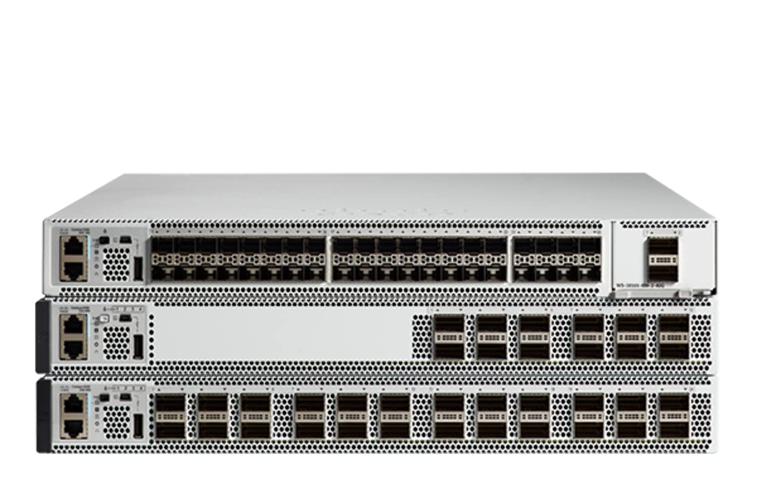
Figure 4.1: Front Panel of the Cisco Catalyst 9500 C9500-24Y4C-A Switch. This image displays the front of the switch, featuring 24 SFP/SFP+/SFP28 ports for high-speed fiber and copper connectivity, along with 4 QSFP28 ports for even higher bandwidth uplinks. Various status LEDs and management ports are also visible.
4.1 Front Panel Features
- 24 x SFP/SFP+/SFP28 Ports: These ports support various fiber and copper transceivers for flexible network connectivity at speeds up to 25 Gbps.
- 4 x QSFP28 Ports: High-density quad small form-factor pluggable ports for 100 Gbps uplinks or stacking.
- Status LEDs: Indicators for system status, port activity, and power. Refer to the LED section for detailed explanations.
- Console Port: RJ-45 port for out-of-band management via a serial connection.
- USB Port: For software upgrades or configuration backup/restore.
4.2 Rear Panel Features
- Power Supply Modules: Slots for redundant power supplies.
- Fan Modules: Slots for hot-swappable fan modules.
- Grounding Lug: For connecting the chassis to earth ground.
5. Setup and Installation
5.1 Site Preparation
- Ensure the installation site is clean, dry, and well-ventilated.
- Maintain ambient temperature within the specified operating range (up to 40°C).
- Provide adequate space for airflow around the switch.
- Ensure a reliable power source with proper grounding.
5.2 Rack Mounting
The switch is designed for standard 19-inch rack mounting.
- Attach the provided rack-mount brackets to the sides of the switch using the supplied screws.
- Align the switch with the rack posts and secure it using appropriate rack screws.
- Ensure the switch is level and securely fastened.
5.3 Connecting Power
- Insert the power cord into the power supply module on the rear of the switch.
- Connect the other end of the power cord to a grounded AC power outlet.
- If using redundant power supplies, connect both to separate power sources for maximum reliability.
5.4 Network Connections
- Insert appropriate SFP/SFP+/SFP28 transceivers into the desired front panel ports.
- Connect fiber optic or copper cables from your network devices to the installed transceivers.
- For high-speed uplinks or stacking, insert QSFP28 transceivers and connect compatible cables.
5.5 Initial Configuration Access
To perform initial configuration, connect a console cable from your management workstation to the console port on the switch's front panel. Use a terminal emulation program (e.g., PuTTY, Tera Term) with the following settings:
- Baud Rate: 9600
- Data Bits: 8
- Parity: None
- Stop Bits: 1
- Flow Control: None
6. Operating the Switch
6.1 Powering On/Off
- Power On: After connecting the power cords, the switch will automatically power on. Observe the system LEDs for boot-up status.
- Power Off: To power off, disconnect the power cords from the power source. For graceful shutdown, it is recommended to save the configuration and issue a shutdown command via the CLI before disconnecting power.
6.2 LED Indicators
The front panel LEDs provide visual status of the switch's operation:
- System LED: Indicates overall system health (e.g., green for normal, amber for warning, red for critical).
- Port Status LEDs: Indicate link status and activity for each network port (e.g., green for link, blinking for activity, off for no link).
- Power Supply LEDs: Indicate the status of installed power supply units.
6.3 Management Interfaces
- Command Line Interface (CLI): Accessed via the console port or SSH/Telnet (after initial configuration). Provides full control over the switch.
- Web User Interface (Web UI): Accessed via a web browser (after initial IP configuration). Offers a graphical interface for common tasks.
- SNMP: For network management system integration.
7. Maintenance
7.1 Firmware Updates
Regularly check the Cisco support website for the latest firmware updates. Keeping the firmware up-to-date ensures optimal performance, security, and access to new features. Follow the specific upgrade procedures provided by Cisco.
7.2 Cleaning
- Ensure the switch is powered off and disconnected from the power source before cleaning.
- Use a soft, dry cloth to wipe the exterior of the switch.
- Do not use liquid or aerosol cleaners.
- Keep ventilation openings clear of dust and debris.
7.3 Environmental Considerations
Maintain the operating environment within specified limits to prevent overheating and ensure longevity. Monitor ambient temperature and humidity. Ensure proper airflow through the rack and around the switch.
8. Troubleshooting
This section provides solutions to common issues you might encounter.
8.1 No Power
- Verify that the power cord is securely connected to both the switch and the power outlet.
- Check the power outlet with another device to ensure it is functional.
- Ensure the power supply modules are correctly seated in their slots.
8.2 No Link on Port
- Check the cable connection between the switch port and the connected device.
- Ensure the correct transceiver (SFP/SFP+/SFP28) is used and properly seated.
- Verify that the connected device is powered on and functioning correctly.
- Check the port configuration on the switch (e.g., speed, duplex, shutdown status) via CLI or Web UI.
8.3 Connectivity Issues
- Verify IP address, subnet mask, and gateway settings on the switch and connected devices.
- Check VLAN configurations to ensure devices are in the correct broadcast domain.
- Examine routing tables if devices are on different subnets.
- Use diagnostic tools like ping and traceroute from the switch CLI.
8.4 System LED Indicates Error
If the System LED is amber or red, consult the Cisco documentation for specific error codes or patterns. This usually indicates a hardware fault or a critical system issue. Contact Cisco Technical Support if the issue persists.
9. Specifications
Key technical specifications for the Cisco Catalyst 9500 C9500-24Y4C-A Switch:
| Feature | Specification |
|---|---|
| Brand | Cisco |
| Model Number | C9500-24Y4C-A |
| Number of Ports | 24 x SFP/SFP+/SFP28, 4 x QSFP28 |
| Interface Type | SFP, SFP+, SFP28, QSFP28 |
| Data Transfer Rate | Up to 25 Gigabits Per Second (per SFP28 port) |
| Upper Temperature Rating | 40 Degrees Celsius |
| Case Material | Metal |
| Compatible Devices | Desktop (for management workstation) |
| Manufacturer | CISCO SYSTEMS - ENTERPRISE |
| UPC | 649661945130 |
10. Warranty and Support
This product is a renewed item. For specific warranty information, please refer to the Amazon Renewed Guarantee details provided at the time of purchase. For technical support, documentation, and software downloads, please visit the official Cisco support website or contact your authorized Cisco reseller.
Amazon Renewed Guarantee: Renewed products are eligible for replacement or refund under the Amazon Renewed Guarantee if not satisfied with the purchase.


