1. Introduction
This manual provides essential information for the installation, operation, and maintenance of your FORTINET FS-448E-FPOE Ethernet Switch. The FS-448E-FPOE is a high-performance, 48-port Power over Ethernet (PoE) switch designed for robust network environments, supporting 3-layer functionality, modular configurations, and rack-mountable deployment. It features advanced capabilities such as Universal Zero Trust Network Access (ZTNA) and Secure Access Service Edge (SASE) support.
Please read this manual thoroughly before operating the device to ensure proper usage and to prevent damage.
2. Safety Information
- Power Supply: Use only the power supply provided or specified by FORTINET. Ensure the voltage matches the device requirements (100-240V AC, 50/60Hz).
- Ventilation: Ensure adequate airflow around the device. Do not block ventilation openings. Maintain proper clearance for cooling fans.
- Environment: Operate the switch within the specified temperature (0°C to 50°C) and humidity (10% to 90% non-condensing) ranges. Avoid exposure to direct sunlight, excessive heat, moisture, or dust.
- Grounding: Ensure the device is properly grounded to prevent electrical shock.
- Servicing: Do not attempt to service the device yourself. Refer all servicing to qualified personnel.
3. Package Contents
Verify that your package contains the following items:
- FORTINET FS-448E-FPOE Ethernet Switch
- Power Cord(s)
- Rack-mount Kit (brackets and screws)
- Console Cable (RJ45 to DB9)
- Quick Start Guide
If any items are missing or damaged, contact your vendor immediately.
4. Physical Overview
The FORTINET FS-448E-FPOE switch features a standard 1U rack-mountable design. Below are descriptions of its front and rear panels.
4.1. Front Panel
The front panel provides all network ports, management ports, and status indicators.
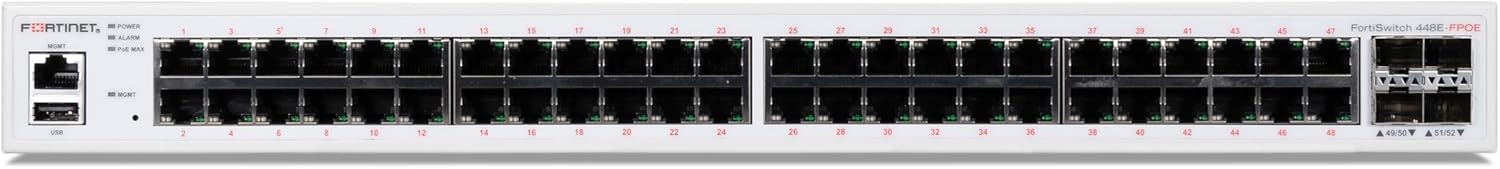
Image 4.1: Front view of the FORTINET FS-448E-FPOE Ethernet Switch, showing 48 RJ45 ports, SFP+ ports, console port, USB port, reset button, and LED indicators.
- RJ45 Ports (1-48): 48x 10/100/1000Base-T Ethernet ports with Power over Ethernet (PoE/PoE+) capabilities.
- SFP+ Ports (49-52): 4x 10 Gigabit Ethernet SFP+ ports for high-speed uplinks.
- Console Port: RJ45 serial console port for local management and initial configuration.
- USB Port: For firmware upgrades or configuration backup/restore.
- Reset Button: Recessed button to reset the device to factory defaults (use with caution).
- LED Indicators:
- POWER: Indicates power status.
- ALARM: Indicates system alarms or errors.
- PoE MAX: Indicates PoE power budget utilization.
- Link/Activity LEDs (per port): Indicate link status and data activity.
4.2. Rear Panel
The rear panel contains the power inputs and cooling components.

Image 4.2: Rear view of the FORTINET FS-448E-FPOE Ethernet Switch, showing dual AC power inputs and cooling fans.
- AC INPUT (x2): Dual redundant AC power inputs (100-240V AC, 50/60Hz) for power redundancy.
- Cooling Fans: Integrated fans for heat dissipation, ensuring optimal operating temperature.
5. Setup
Follow these steps to set up your FORTINET FS-448E-FPOE Ethernet Switch.
5.1. Rack Mounting
The switch is designed for installation in a standard 19-inch equipment rack.
- Attach the provided rack-mount brackets to the sides of the switch using the included screws.
- Secure the switch into the rack using appropriate rack screws. Ensure the switch is level and adequately supported.
5.2. Power Connection
Connect the switch to a power source.
- Connect one or both power cords to the AC INPUT ports on the rear panel of the switch.
- Plug the other end of the power cord(s) into a grounded electrical outlet or a UPS (Uninterruptible Power Supply).
- The switch will power on automatically. Verify the POWER LED on the front panel illuminates.
5.3. Network Connections
Connect your network devices to the switch.
- RJ45 Ports: Connect Ethernet cables from your network devices (e.g., computers, IP phones, wireless access points) to the RJ45 ports (1-48) on the front panel. For PoE-powered devices, ensure they are 802.3af/at compliant.
- SFP+ Ports: For high-speed uplinks to other switches or network devices, insert compatible SFP+ transceivers into the SFP+ ports (49-52) and connect fiber optic cables.
5.4. Console Connection (Optional)
For initial configuration or command-line interface (CLI) access.
- Connect one end of the console cable (RJ45) to the Console port on the switch.
- Connect the other end (DB9) to the serial port of a computer.
- Configure your terminal emulation software (e.g., PuTTY, Tera Term) with the following settings: 9600 baud, 8 data bits, no parity, 1 stop bit, no flow control.
6. Operating the Switch
Once powered on and connected, the switch begins operation. Basic monitoring can be done via the front panel LEDs.
6.1. LED Indicators
Understanding the LED status is crucial for monitoring the switch's health and network activity.
- POWER LED:
- Solid Green: Device is powered on and operating normally.
- Off: Device is powered off or experiencing a power issue.
- ALARM LED:
- Solid Red: Indicates a critical system alarm (e.g., fan failure, over-temperature).
- Flashing Red: Indicates a minor system warning.
- Off: No alarms or warnings.
- PoE MAX LED:
- Solid Amber: PoE power budget is nearing its maximum capacity.
- Flashing Amber: PoE power budget has been exceeded, and some PoE devices may not be powered.
- Off: PoE power budget is within normal limits.
- Link/Activity LEDs (per RJ45/SFP+ port):
- Solid Green/Amber: Indicates a stable network link (speed may vary by color).
- Flashing Green/Amber: Indicates data activity on the port.
- Off: No link detected or port is disabled.
6.2. Management Access
The switch can be managed via a web-based graphical user interface (GUI) or a command-line interface (CLI) through the console port or SSH/Telnet (after initial configuration).
- Web GUI: Access the switch's IP address via a web browser. Refer to the Quick Start Guide or FORTINET documentation for default IP address and login credentials.
- CLI: Use the console port for direct access or SSH/Telnet for remote access.
7. Maintenance
Regular maintenance helps ensure the longevity and optimal performance of your switch.
- Cleaning: Periodically clean the exterior of the switch with a soft, dry cloth. Do not use liquid or aerosol cleaners. Ensure ventilation openings are free from dust and debris.
- Firmware Updates: Regularly check the FORTINET support website for the latest firmware updates. Applying updates can improve performance, add features, and address security vulnerabilities. Follow FORTINET's official update procedures carefully.
- Environmental Monitoring: Ensure the operating environment remains within specified temperature and humidity ranges to prevent overheating or condensation.
- Cable Management: Keep network cables organized and properly secured to prevent accidental disconnections or damage.
8. Troubleshooting
This section provides solutions to common issues you might encounter.
| Problem | Possible Cause | Solution |
|---|---|---|
| No Power (POWER LED Off) | Power cord disconnected; Power outlet failure; Internal power supply issue. | Check power cord connections; Try a different power outlet; If issue persists, contact support. |
| No Link on a Port (Link LED Off) | Cable disconnected or faulty; Device not powered on; Port disabled; Incorrect cable type. | Verify cable connection; Check connected device power; Ensure port is enabled in configuration; Use correct Ethernet or fiber cable. |
| Network Connectivity Issues | Incorrect IP configuration; VLAN mismatch; Firmware issue; Cable problem. | Verify IP settings on devices and switch; Check VLAN configurations; Update firmware; Test with different cables. |
| ALARM LED is Red | System error (e.g., fan failure, high temperature). | Check fan operation; Ensure proper ventilation; Consult system logs via CLI/GUI for specific error messages. |
| PoE Devices Not Powering On | PoE budget exceeded; Device not PoE compliant; Cable issue; Port disabled. | Check PoE MAX LED; Verify device PoE compliance; Use a known good Ethernet cable; Ensure PoE is enabled on the port. |
8.1. Factory Reset
If the switch is unresponsive or you need to clear all configurations, you can perform a factory reset. Warning: This will erase all configurations and restore the switch to its default settings.
- With the switch powered on, use a paperclip or a similar pointed object to press and hold the recessed Reset button on the front panel for approximately 10-15 seconds.
- Release the button when the LEDs indicate a reset sequence (e.g., all LEDs flash).
- The switch will reboot with factory default settings.
9. Specifications
Detailed technical specifications for the FORTINET FS-448E-FPOE Ethernet Switch.

Image 9.1: Detailed specifications for the FortiSwitch 448E-FPOE, including hardware, system, and environmental parameters.
| Feature | Specification |
|---|---|
| Model | FS-448E-FPOE |
| Interface Type | PoE |
| Number of Ports | 48x GE RJ45 and 4x 10GE SFP+ ports |
| Form Factor | 1 RU Rack Mount |
| PoE Standard | 802.3af/at |
| PoE Power Budget | 772 W |
| Mean Time Between Failures (MTBF) | > 10 years |
| Switching Capacity (Duplex) | 176 Gbps |
| Packets Per Second (Duplex) | 262 Mpps |
| MAC Address Storage | 32 K |
| Network Latency | < 1µs |
| VLANs Supported | 4K |
| DRAM | 1GB DDR4 |
| Flash | 256 MB |
| Product Dimensions (H x D x W) | 1.73 x 16.1 x 17.3 inches (44 x 410 x 440 mm) |
| Item Weight | 14.04 pounds (6.37 kg) |
| Power Required | 100-240V AC, 50/60 Hz |
| Power Supply | AC built-in |
| Redundant Power | Redundant AC |
| Heat Dissipation | 163.1 BTU/h |
| Operating Temperature | 32°-122°F (0°-50°C) |
| Storage Temperature | -4°-158°F (-20°-70°C) |
| Humidity | 10%-90% non-condensing |
| Airflow Direction | Side-to-side |
| Noise Level | 50.7 dBA |
10. Warranty Information
FORTINET products are covered by a limited warranty. For the FS-448E-FPOE Ethernet Switch, a Limited Lifetime Warranty applies to all models. Please refer to the official FORTINET warranty policy document available on their website for full terms and conditions, including details on coverage, duration, and procedures for warranty claims.
Note: PoE power consumption is similar to non-PoE models if PoE is not in use.
11. Technical Support
For technical assistance, product documentation, or to report issues, please contact FORTINET support through the following channels:
- FORTINET Support Website: Visit www.fortinet.com/support for knowledge base articles, downloads, and support portals.
- Contact Information: Refer to the FORTINET website for regional support phone numbers and email contacts.
Before contacting support, please have your product model (FS-448E-FPOE) and serial number ready.


