1. Product Overview
The LoraTap Wireless Light Switch with Remote Control and Pulse Relay Module is designed for convenient control of various electrical devices, including door openers and automatic gates. It provides a clean contact output, making it versatile for integration into existing systems. The system consists of a wireless transmitter (switch) and a relay receiver.

Image 1.1: LoraTap Wireless Light Switch (Transmitter) and Relay Module (Receiver).
2. Important Safety Information
Read all safety information before product use.

Image 2.1: Safety warnings provided by the manufacturer.
- RISK OF ELECTRIC SHOCK OR FIRE: Improper use or installation can cause SERIOUS INJURY, DEATH, or LOSS/DAMAGE OF PROPERTY. TURN OFF power supply before installing, servicing, or removing the receiver. Use a non-contact voltage tester to ensure the power is off.
- The receiver must be installed by a licensed electrician in accordance with all national and local electrical codes. If you are unsure about any part of these instructions, consult a qualified electrician.
- For indoor use only. For permanently installed fixtures only.
- Do not immerse product in any liquid or expose to heat or moisture.
3. Package Contents
The package includes the following items:
- 1 x Relay Receiver
- 1 x Switch (Remote Control)
- 1 x Magnetic Switch Base
- 1 x CR2032 Battery (pre-installed in remote control)
- 1 x Double-sided adhesive
- 1 x Screwdriver
- 1 x User Manual in English

Image 3.1: Front view of the product packaging, showing included components and basic specifications.
4. Specifications
Transmitter (Remote Control)
- Color: White
- Button: 1 Button, ON/OFF
- Signal Range: Up to 30-60m (indoor), up to 200m (outdoor, depending on local circumstances)
- Frequency: 868Mhz
- Duration: Over 220 thousand clicks
- Battery Type: CR2032 (Included)
- Battery Life: Up to 10 years
- Size (Diameter x Height): 6.8 x 1.5 cm
Relay Receiver
- Color: White
- Input: 85-265VAC, 50/60Hz
- Output: 85-265VAC, 50/60Hz (Clean Contact)
- Max Load: 10 Amp
- Maximum Power: LED, CFL, fluorescent bulbs: 300W; Incandescent, tungsten, halogen bulbs: 2500W
- LED Light Coloration: White
- Size (H x W x L): 4.8 x 4.2 x 2.2 cm
- Note: Relay receiver cannot work with other brand dimmers.

Image 4.1: Detailed dimensions of the wireless switch and relay module.
5. Setup and Installation
5.1. Wiring the Relay Receiver
WARNING: Ensure power is OFF before performing any wiring. Consult a qualified electrician if unsure.
The relay receiver provides a clean contact output, suitable for controlling devices like gate openers or garage doors that require a momentary dry contact signal.
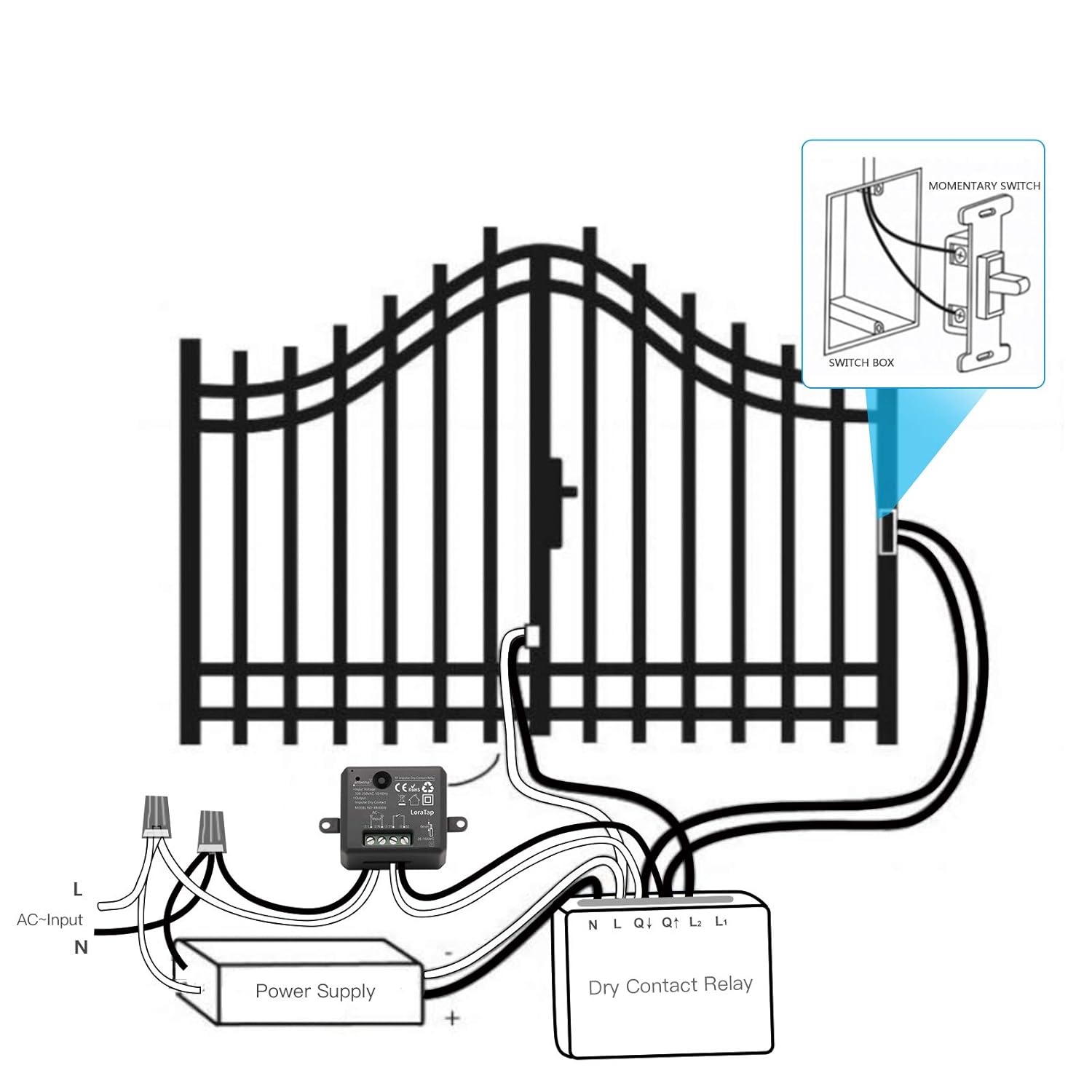
Image 5.1: Example wiring diagram for connecting the relay module to a gate opener system.
For more complex setups involving access control systems, refer to the following diagram:
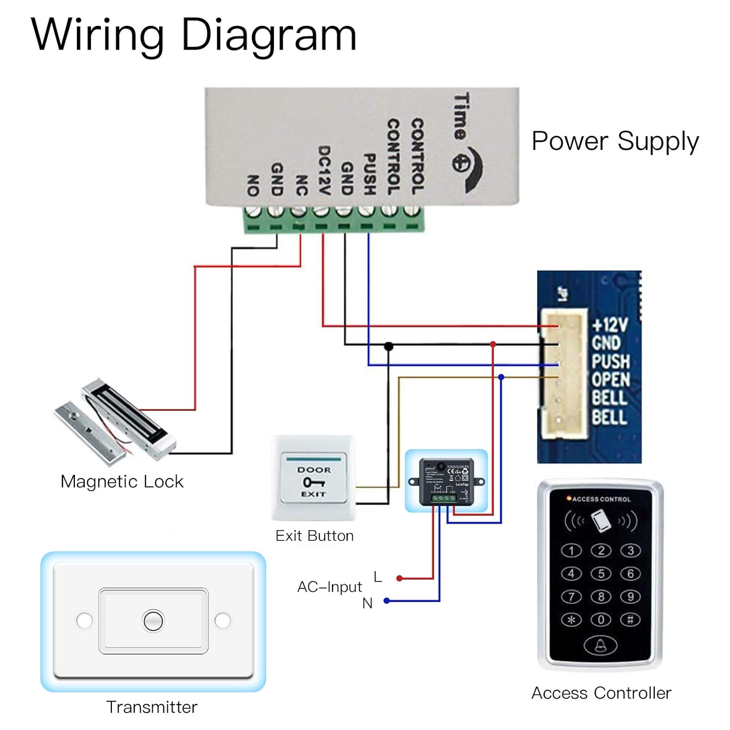
Image 5.2: Detailed wiring diagram showing integration with a power supply, magnetic lock, exit button, and access controller.
5.2. Installing the Wireless Switch (Transmitter)
The wireless switch can be installed in two modes: Fixed Mode (mounted to a wall) or Portable Mode (used as a remote control).

Image 5.3: Illustration of Fixed Mode (wall-mounted) and Portable Mode (handheld remote) for the wireless switch.
For fixed installation using the magnetic switch base:
- Tear off the adhesive tape from the back of the magnetic switch base.
- Stick the base firmly to the desired wall surface using the adhesive tape.
- Attach the wireless transmitter (switch) onto the base. It will be held in place by magnetic force.

Image 5.4: Step-by-step guide for easy installation of the wireless switch base.
6. Operating Instructions
Once the relay receiver is wired and powered, and the wireless switch is installed, the system is ready for operation.
- Press the button on the wireless switch to activate the relay module. The relay will provide a momentary clean contact signal, typically used to trigger devices like gate openers or garage doors.
- The signal range varies based on environment:
- Indoor Control Range: Up to 30-60 meters. The strong signal can pass through walls, windows, and ceilings.
- Outdoor Control Range: Up to 200 meters (in open areas with no barriers).

Image 6.1: Illustration of the effective indoor and outdoor control ranges for the wireless system.
7. Maintenance
- Battery Replacement: The wireless switch uses a CR2032 battery with an estimated life of up to 10 years. If the switch becomes unresponsive, replace the battery. Use the provided screwdriver to open the switch casing carefully.
- Cleaning: Wipe the devices with a soft, dry cloth. Do not use abrasive cleaners or immerse in water.
- Environmental Conditions: Ensure the devices are kept away from excessive heat, moisture, and direct sunlight to prolong their lifespan.
8. Troubleshooting
| Problem | Possible Cause | Solution |
|---|---|---|
| Wireless switch does not activate the relay. | Low or dead battery in the wireless switch. Out of range. Interference. Incorrect wiring of the relay receiver. | Replace the CR2032 battery. Move the switch closer to the receiver. Relocate the receiver or switch to avoid interference sources. Verify wiring according to diagrams in Section 5.1. Ensure power is off before checking wiring. |
| Relay receiver not powering on. | No power supply to the receiver. Incorrect input voltage. | Check power connections and circuit breaker. Ensure input voltage is within 85-265VAC. |
| Device connected to relay does not respond. | Device itself is faulty. Incorrect connection to the device. Overload on the relay. | Test the connected device independently. Verify the clean contact output from the relay is correctly connected to the device's trigger input. Ensure the load does not exceed 10 Amp or the specified wattage for the bulb type. |
9. Warranty and Support
For warranty information or technical support, please contact LoraTap customer service through the retailer where the product was purchased or visit the official LoraTap website. Please have your model number (TM4386) and purchase details ready when contacting support.