1. Introduction
The COMPUTHERM T32-RF is a wireless digital room thermostat designed to control most boilers and air conditioning systems. It offers precise temperature measurement and adjustment, contributing to both comfort and energy efficiency. The system consists of two main units: a portable thermostat (control unit) and a receiver unit. These units communicate wirelessly via radio frequency, eliminating the need for complex wired installations. Each unit is pre-paired with a unique security code to ensure reliable operation.
2. Safety Information
- Professional Installation: The receiver unit, which connects to your heating or cooling system, must be installed by a qualified electrician or heating engineer to ensure safety and proper functionality.
- Power Supply: Ensure the main power supply to the heating/cooling system is disconnected before installing or servicing the receiver unit.
- Battery Safety: Use only the specified battery type (2x AAA 1.5V alkaline). Do not mix old and new batteries, or different types of batteries. Dispose of used batteries responsibly.
- Environmental Protection: The thermostat has an IP20 rating, meaning it is protected against solid objects larger than 12.5mm but has no protection against water. Avoid exposure to moisture or extreme temperatures.
- Intended Use: This device is intended for indoor use only to control room temperature. Do not use it for purposes other than those specified in this manual.
3. Package Contents
Please check the package for the following items:
- 1x COMPUTHERM T32-RF Wireless Digital Room Thermostat (Control Unit)
- 1x COMPUTHERM T32-RF Receiver Unit
- 2x AAA 1.5V Alkaline Batteries
- 1x Power Cable for Receiver
- Mounting accessories (screws and wall plugs)
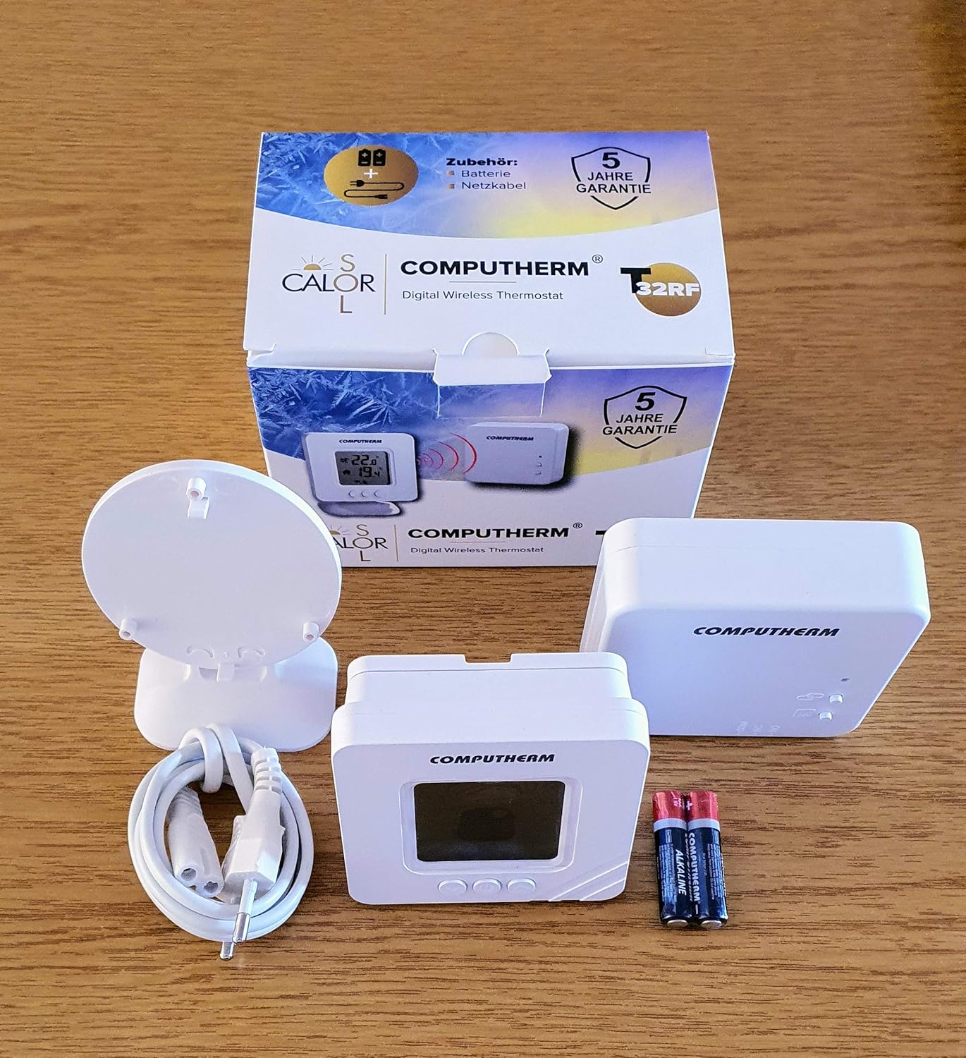
Image: Contents of the COMPUTHERM T32-RF package, showing the thermostat, receiver, batteries, and connecting cables.
4. Product Overview
4.1. Thermostat (Control Unit)

Image: Front view of the COMPUTHERM T32-RF thermostat, showing the digital display with current and set temperatures, battery indicator, and control buttons.
The thermostat unit features a digital display and three control buttons:
- Display: Shows current room temperature, set temperature, battery status, and heating/cooling indicators (flame for heating, snowflake for cooling).
- Up Button (▲): Increases the set temperature.
- Down Button (▼): Decreases the set temperature.
- Power/Mode Button (Ⓘ): Turns the thermostat on/off and may switch between operating modes (refer to specific operating instructions for mode switching).
4.2. Receiver Unit

Image: The COMPUTHERM T32-RF receiver unit, a white rectangular box with indicator lights and control buttons for linking and manual override.
The receiver unit connects directly to your boiler or air conditioner. It receives commands wirelessly from the thermostat and controls the heating/cooling system. It typically includes indicator lights for power and relay status, and a button for manual override or pairing (though units are pre-paired).
5. Setup
5.1. Receiver Unit Installation
Important: This step must be performed by a qualified professional. Ensure the main power supply is disconnected before proceeding.
- Mount the receiver unit in a suitable location near your boiler or air conditioner, away from direct heat sources or drafts.
- Connect the receiver unit to the two-wire control circuit of your boiler (24V or 230V) or air conditioner according to the wiring diagram provided with your heating/cooling system and the receiver unit.
- Connect the receiver unit to its power supply using the provided power cable.
- Once wiring is complete, restore the main power supply. The receiver's indicator light should illuminate.
5.2. Thermostat Battery Installation
- Open the battery compartment on the back of the thermostat unit.
- Insert two (2) AAA 1.5V alkaline batteries, ensuring correct polarity (+/-).
- Close the battery compartment. The thermostat display should turn on.
5.3. Initial Pairing (Units are Pre-Paired)
The COMPUTHERM T32-RF thermostat and receiver units are pre-paired at the factory. No manual pairing is typically required for initial setup. If communication issues arise, refer to the Troubleshooting section.
5.4. Thermostat Placement
Place the portable thermostat unit in the room where you want to measure and control the temperature. For accurate readings, avoid placing it:
- Near heat sources (e.g., radiators, direct sunlight, lamps).
- In direct drafts (e.g., near windows, doors).
- In areas with high humidity.

Image: The included mounting plate and stand, allowing the thermostat to be placed on a surface or mounted on a wall.
6. Operating Instructions
6.1. Power On/Off
Press the Power/Mode (Ⓘ) button to turn the thermostat on or off.
6.2. Setting the Desired Temperature
- When the thermostat is on, the display shows the current room temperature and the set temperature.
- Use the Up (▲) or Down (▼) buttons to adjust the desired temperature. The set temperature range is +5 °C to +30 °C, adjustable in 0.5 °C increments.
- The thermostat will automatically save the new setting after a few seconds of inactivity.
6.3. Heating and Cooling Control
The thermostat automatically controls heating or cooling based on the set temperature and the current room temperature, with a switching sensitivity of ± 0.2 °C or 0.1 °C.
- Heating Mode: If the current room temperature falls below the set temperature (minus the sensitivity), the thermostat sends a signal to the receiver to activate the heating system. A flame icon will appear on the display.
- Cooling Mode: If the current room temperature rises above the set temperature (plus the sensitivity), the thermostat sends a signal to the receiver to activate the cooling system. A snowflake icon will appear on the display.
6.4. Temperature Calibration
If you find the displayed temperature inaccurate, you can calibrate it:
- Refer to the full product manual for specific instructions on entering calibration mode (this usually involves pressing a combination of buttons).
- Adjust the calibration value within the range of ± 8.0 °C in 0.5 °C increments using the Up/Down buttons.
- Confirm the setting to save the calibration.
7. Maintenance
7.1. Battery Replacement
When the low battery indicator appears on the thermostat display, replace the batteries promptly to ensure continuous operation. The expected battery life is approximately 1 year.
- Open the battery compartment on the back of the thermostat.
- Remove the old AAA batteries.
- Insert two new AAA 1.5V alkaline batteries, observing correct polarity.
- Close the battery compartment.
7.2. Cleaning
Clean the thermostat and receiver units with a soft, dry cloth. Do not use abrasive cleaners, solvents, or immerse the units in water.
8. Troubleshooting
| Problem | Possible Cause | Solution |
|---|---|---|
| Thermostat display is blank. | Dead or incorrectly inserted batteries. | Replace batteries with new AAA 1.5V alkaline batteries, ensuring correct polarity. |
| Heating/Cooling system not responding. | No power to receiver; receiver not correctly wired; communication issue between thermostat and receiver. | Check power to receiver. Verify receiver wiring (professional assistance recommended). Ensure thermostat is within range of receiver (approx. 100m open space). If issues persist, consult the full manual for re-pairing instructions or contact support. |
| Short battery life (e.g., 2 weeks). | Low-quality batteries; frequent communication due to placement; environmental factors. | Use high-quality alkaline batteries from reputable brands. Ensure thermostat is not placed in an area requiring constant adjustments or frequent communication. |
| Relay cycles continuously when demand is active. | Faulty receiver relay; incorrect wiring; system incompatibility. | Verify wiring with a qualified professional. If the issue persists, the receiver unit may be faulty and require replacement. Contact customer support. |
| Inaccurate temperature reading. | Thermostat placement; need for calibration. | Relocate thermostat away from heat sources or drafts. Perform temperature calibration as described in section 6.4. |
9. Specifications
| Feature | Specification |
|---|---|
| Brand | COMPUTHERM |
| Model Number | T32-RF |
| Temperature Measurement Range | -9.9 °C to +50 °C (in 0.1 °C increments) |
| Adjustable Temperature Range | +5 °C to +30 °C (in 0.5 °C increments) |
| Temperature Measurement Accuracy | ± 0.5 °C |
| Temperature Calibration Range | ± 8.0 °C (in 0.5 °C increments) |
| Switching Sensitivity | ± 0.2 °C or 0.1 °C |
| Storage Temperature | -20 °C to +60 °C |
| Thermostat Battery | 2x 1.5V AAA Alkaline (LR03) |
| Expected Battery Life | Approx. 1 year |
| Environmental Protection | IP20 |
| Operating Frequency | 433 MHz |
| Wireless Range | Approx. 100 m (in open space) |
| Thermostat Dimensions (L x W x H) | 85 x 85 x 27.5 mm |
| Thermostat Weight | 75 g |
| Total Device Weight (Thermostat + Receiver + Console) | 210 g |
| Receiver Voltage | 230 Volts |
| Connectivity Technology | RF (Radio Frequency) |
| Controller Type | Push-button |
| Special Feature | Portable |
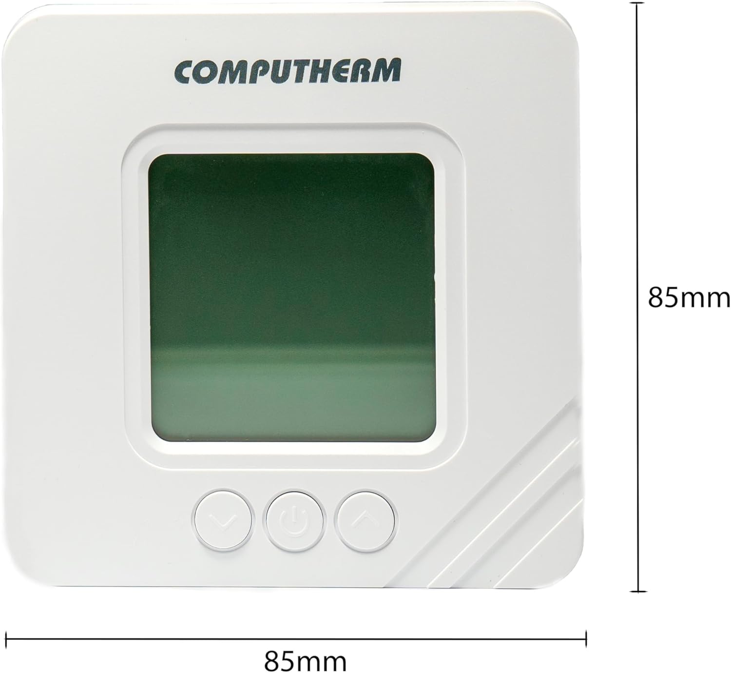
Image: Front dimensions of the COMPUTHERM T32-RF thermostat, indicating 85mm width and 85mm height.

Image: Side dimensions of the COMPUTHERM T32-RF thermostat, indicating a depth of 27.5mm.
10. Warranty and Support
10.1. Warranty
The COMPUTHERM T32-RF Wireless Digital Thermostat comes with a 5-year manufacturer's warranty. Please retain your proof of purchase for warranty claims. The warranty covers defects in materials and workmanship under normal use.
10.2. Customer Support
For technical assistance, troubleshooting, or warranty inquiries, please visit the manufacturer's website or contact their customer support. You can find more information at:

Image: Close-up of the product packaging, highlighting the manufacturer's website for support: www.calorsol.de.


