
1. Introduction
This manual provides detailed instructions for the safe and efficient operation, setup, and maintenance of the RS PRO IPS 4303 Laboratory DC Power Supply. The IPS 4303 is a versatile benchtop digital DC power supply designed for various laboratory and industrial applications, offering precise control over voltage and current outputs.
Key features include multiple output channels, digital displays for accurate readings, and various operating modes such as independent, series, parallel, and tracking. This model provides outputs of 5.2V, 15V, and 30V with corresponding currents of 1A and 3A, delivering a total power of 200W via an IEC320 connector.
2. Safety Information
To ensure safe operation and prevent damage to the device or injury to personnel, please read and adhere to the following safety precautions:
- Always connect the power supply to a grounded AC outlet.
- Do not operate the device in wet or damp conditions.
- Ensure proper ventilation to prevent overheating.
- Do not open the casing; there are no user-serviceable parts inside. Refer servicing to qualified personnel.
- Verify that the input voltage matches the power supply's rating before connecting to mains power.
- Avoid short-circuiting the output terminals for extended periods.
- Disconnect power before making any connections or disconnections to the output terminals.
3. Product Overview
The RS PRO IPS 4303 features a clear front panel with digital displays and intuitive controls for precise adjustments.
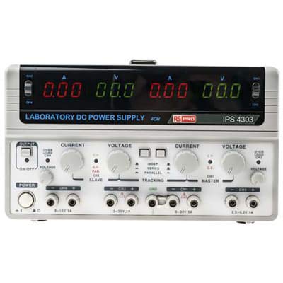
Image: Front panel of the RS PRO IPS 4303 Laboratory DC Power Supply. The top section features digital displays for voltage and current. The bottom section includes power controls, current and voltage adjustment knobs for multiple channels, output terminals, and mode selection buttons for independent, series, parallel, and tracking operations.
3.1 Front Panel Controls and Indicators
- Power ON/OFF Switch: Main power switch for the unit.
- Output ON/OFF Switch: Controls the activation of the output terminals.
- Current Adjustment Knobs (CH1, CH2, CH3): Fine and coarse controls for setting the output current limit for each channel.
- Voltage Adjustment Knobs (CH1, CH2, CH3): Fine and coarse controls for setting the output voltage for each channel.
- Digital Displays (A, V): LED displays showing the real-time output current (Amperes) and voltage (Volts) for each channel.
- Mode Selection Buttons: Buttons to select between Independent, Series, Parallel, and Tracking modes for multi-channel operation.
- Output Terminals (CH1, CH2, CH3, GND): Binding posts for connecting loads to the power supply.
4. Setup
4.1 Unpacking and Inspection
Carefully remove the power supply from its packaging. Inspect the unit for any signs of physical damage that may have occurred during transit. Retain the packaging materials for future transport or storage.
4.2 Power Connection
Connect the provided power cord to the IEC320 connector on the rear panel of the power supply and then to a suitable grounded AC power outlet. Ensure the mains voltage matches the rating specified on the device.
4.3 Initial Power On
After connecting the power cord, press the main Power ON/OFF switch on the front panel. The digital displays should illuminate, indicating that the unit is receiving power. Verify that the displays show zero or minimal readings before connecting any load.
5. Operating Instructions
5.1 Basic Operation (Independent Mode)
- Ensure the power supply is turned on and the output is off.
- Select the desired channel (e.g., CH1) for independent operation.
- Adjust the Voltage knob to set the desired output voltage. Observe the voltage display.
- Adjust the Current knob to set the desired current limit. This acts as a protection mechanism.
- Connect your load to the corresponding output terminals (e.g., CH1 positive and negative).
- Press the Output ON/OFF switch to activate the output. The displays will show the actual voltage and current delivered to the load.
5.2 Series and Parallel Operation
The IPS 4303 supports series and parallel connections for increased voltage or current output, respectively. Refer to the specific connection diagrams provided in the full product documentation for detailed setup. Use the mode selection buttons to configure the channels for series or parallel operation.
5.3 Tracking Mode
In tracking mode, one channel (master) controls the output of other channels (slaves), allowing for synchronized voltage or current adjustments. This is useful for applications requiring multiple, proportionally controlled power sources. Activate tracking mode using the dedicated button and adjust the master channel's controls.
6. Maintenance
Regular maintenance ensures the longevity and optimal performance of your power supply.
6.1 Cleaning
Wipe the exterior of the unit with a soft, dry cloth. For stubborn dirt, use a slightly damp cloth with a mild detergent. Ensure no liquid enters the ventilation openings or controls. Do not use abrasive cleaners or solvents.
6.2 Calibration
The power supply is factory calibrated. If precise measurements are critical and you suspect a deviation, professional calibration services may be required. Do not attempt to calibrate the unit yourself.
7. Troubleshooting
This section addresses common issues you might encounter with the RS PRO IPS 4303 power supply.
- No Power: Check the power cord connection, the main power switch, and the wall outlet. Verify the fuse if accessible and replaceable by the user (refer to full documentation).
- No Output Voltage/Current: Ensure the Output ON/OFF switch is engaged. Check that voltage and current limits are set above zero. Verify load connections.
- Incorrect Readings: Ensure proper connections to the load. If readings are consistently inaccurate, professional calibration may be needed.
- Overload/Protection Activated: If the power supply enters a protection state (e.g., constant current mode), reduce the load or increase the current limit setting.
8. Specifications
| Parameter | Value |
|---|---|
| Model | IPS 4303 |
| Type | Benchtop Digital DC Power Supply |
| Output Voltage (Channel 1) | 0-5.2V |
| Output Current (Channel 1) | 0-1A |
| Output Voltage (Channel 2) | 0-15V |
| Output Current (Channel 2) | 0-3A |
| Output Voltage (Channel 3) | 0-30V |
| Output Current (Channel 3) | 0-3A |
| Total Power | 200W |
| Power Connector | IEC320 |
| Brand | RS PRO |
9. Warranty and Support
RS PRO products are manufactured to high standards and are typically covered by a manufacturer's warranty against defects in materials and workmanship. For specific warranty terms, duration, and to obtain technical support or service, please refer to the documentation included with your purchase or visit the official RS PRO website. Keep your purchase receipt as proof of purchase.