1. Safety Information
Please read and understand all safety information before operating the Triplett CM650 Clamp Meter. Failure to follow these instructions may result in electric shock, fire, or serious injury.
- Always adhere to local and national safety codes.
- Do not use the meter if it appears damaged or if the test leads are damaged.
- Ensure the meter is set to the correct function and range before making measurements.
- Do not exceed the maximum input limits for any function. The CM650 is rated CAT III-600V.
- Use caution when working with voltages above 30V AC RMS, 42V peak, or 60V DC, as these pose a shock hazard.
- Keep fingers behind the finger guards on the test leads during use.
- Replace batteries immediately when the low battery indicator appears to ensure accurate readings.
- Do not operate the meter in explosive gas, vapor, or dust environments.
2. Product Overview
The Triplett CM650 is a True RMS 6000-count AC/DC clamp meter designed for accurate electrical measurements. It features a large backlit LCD, inrush current measurement, and a non-contact voltage detector.
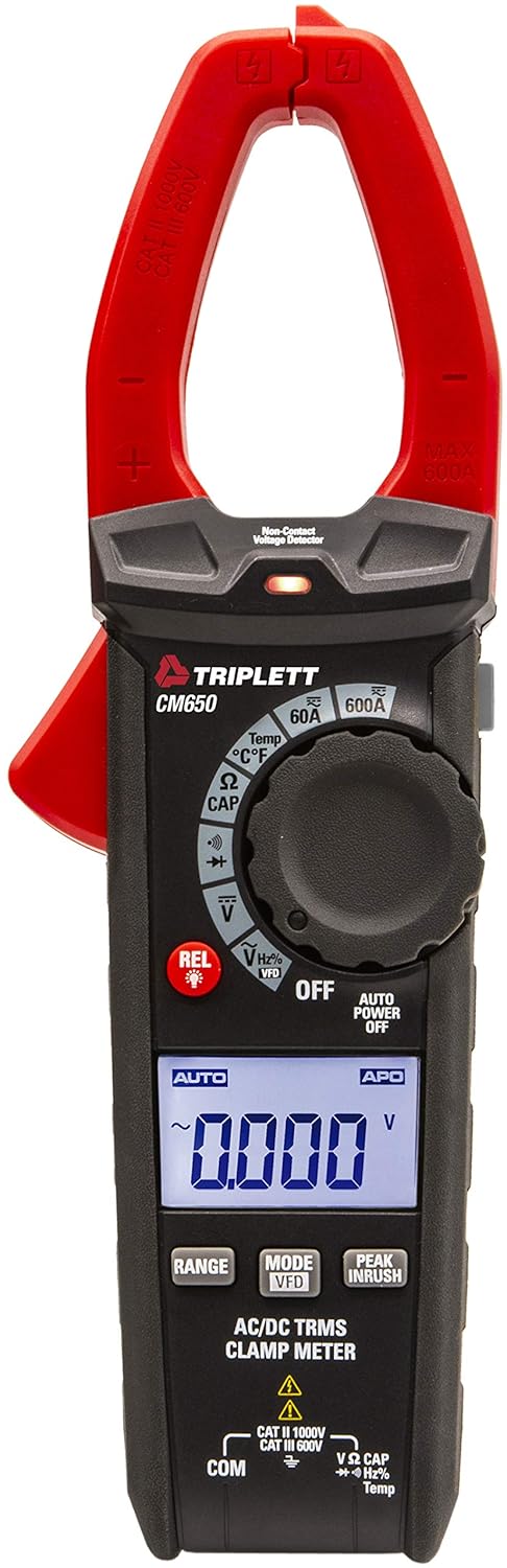
Figure 2.1: Front view of the Triplett CM650 True RMS 600A AC/DC Clamp Meter. This image displays the meter's main body, the red clamp jaws, the rotary dial, the LCD screen, and the function buttons.
2.1 Components and Controls
- Clamp Jaws: Used for non-contact AC/DC current measurement.
- Clamp Trigger: Opens and closes the clamp jaws.
- Rotary Function Switch: Selects the desired measurement function.
- LCD Display: 6000-count backlit display for reading measurements.
- Function Buttons: Include RANGE, MODE/VFD, PEAK INRUSH, REL/Light, and Data Hold.
- Input Jacks: For connecting test leads (COM, VΩCAPHzTemp).
- NCV Sensor: Non-Contact Voltage detection sensor.
- Flashlight: Integrated LED light for illuminating work areas.

Figure 2.2: Close-up view of the Triplett CM650's rotary dial and function buttons. This image highlights the various measurement selections such as 60A, 600A, Temperature, Resistance/Capacitance, Continuity/Diode, Voltage, and VFD mode, along with the REL and backlight button.
3. Setup
3.1 Battery Installation
The CM650 requires 3 AAA batteries (included). To install or replace batteries:
- Ensure the meter is OFF and disconnect all test leads.
- Locate the battery compartment on the rear of the meter.
- Use a screwdriver to open the battery compartment cover.
- Insert the 3 AAA batteries, observing correct polarity (+/-).
- Replace the battery compartment cover and secure it with the screw.
3.2 Connecting Test Leads
For voltage, resistance, capacitance, frequency, temperature, diode, and continuity measurements, connect the test leads as follows:
- Insert the black test lead into the COM input jack.
- Insert the red test lead into the VΩCAPHzTemp input jack.

Figure 3.1: The Triplett CM650 clamp meter shown with its included accessories: test leads, K-type thermocouple probe, and a soft carrying case. This illustrates the complete package provided with the device.
4. Operating Instructions
Turn the rotary switch to the desired function to begin measurement. The meter features an automatic shutdown function to conserve battery life, which can be deactivated if needed.
4.1 AC/DC Current Measurement (Clamp)
To measure AC or DC current up to 600A without breaking the circuit:
- Turn the rotary switch to the 60A or 600A AC/DC current range.
- Press the clamp trigger to open the jaws.
- Enclose only one conductor within the clamp jaws. Ensure the jaws are fully closed.
- Read the current value on the LCD display.

Figure 4.1: A hand holding the Triplett CM650 clamp meter, with its jaws clamped around a single wire within an electrical panel, demonstrating how to measure current. The display shows a reading of 60.0 A.

Figure 4.2: The Triplett CM650 clamp meter being used to measure current on a wire connected to an industrial motor. The meter's display shows a reading of 16.00 A, illustrating its application in industrial settings.
4.2 Voltage Measurement (AC/DC)
To measure AC or DC voltage:
- Connect the test leads to the appropriate input jacks (COM and VΩCAPHzTemp).
- Turn the rotary switch to the V (Voltage) position. The meter will auto-range.
- Touch the test probes to the circuit points where voltage is to be measured.
- Read the voltage value on the LCD display.
4.3 Resistance, Capacitance, Frequency, Temperature, Diode, and Continuity
For these measurements, connect the test leads as described in Section 3.2 and select the corresponding function on the rotary switch. Use the MODE button to cycle through sub-functions if necessary (e.g., Resistance, Capacitance, Diode, Continuity share a dial position).
- Resistance (Ω): Measures electrical resistance in Ohms.
- Capacitance (CAP): Measures capacitance in Farads.
- Frequency (Hz): Measures the frequency of an AC signal.
- Temperature (°C/°F): Use the K-type thermocouple probe for temperature measurements.
- Diode Test: Checks the forward voltage drop of a diode.
- Continuity: Emits an audible tone if the circuit has low resistance (continuity).
4.4 Special Functions
- True RMS: Provides accurate readings for non-sinusoidal or noisy AC waveforms.
- Inrush Current (PEAK INRUSH): Captures the instantaneous surge current when electrical equipment is powered on. Press the PEAK INRUSH button to activate this function.
- Low Pass Filter (LPF/VFD): Filters out high-frequency noise and harmonics when measuring variable frequency drives (VFDs). Activate by pressing the MODE button in the voltage function until VFD appears.
- Non-Contact Voltage (NCV): Detects AC voltage without physical contact. Hold the NCV sensor near a live conductor. An LED indicator and audible beep will signal the presence of voltage.
- Relative Mode (REL): Allows for comparisons with a stored reference value. Press the REL button to store the current reading as a reference. Subsequent readings will show the difference from this reference.
- Data Hold: Freezes the current reading on the display. Press the HOLD button to activate/deactivate.
- Min/Max: Records the minimum and maximum values during a measurement session.
- Flashlight: Press the REL/Light button briefly to turn the integrated flashlight on or off.
5. Maintenance
5.1 Cleaning
Wipe the meter with a dry, clean cloth. Do not use abrasives or solvents. Keep the input terminals free of dirt and moisture.
5.2 Battery Replacement
Refer to Section 3.1 for battery replacement instructions. Replace batteries promptly when the low battery indicator appears on the display to ensure accurate measurements.
6. Troubleshooting
| Problem | Possible Cause | Solution |
|---|---|---|
| Meter does not power on | Dead or incorrectly installed batteries | Check battery polarity; replace batteries. |
| No reading or "OL" displayed | Incorrect function/range; open circuit; measurement exceeds range | Select correct function/range; check circuit continuity; ensure measurement is within meter's limits. |
| Inaccurate readings | Low battery; external interference; dirty test leads | Replace batteries; move away from strong electromagnetic fields; clean test leads and input jacks. |
| NCV not detecting voltage | Voltage too low; sensor not close enough; shielded wire | Ensure voltage is present and within detectable range; place sensor closer to conductor; NCV may not work on shielded wires. |
7. Specifications
| Feature | Specification |
|---|---|
| Model | CM650 |
| Display | 6000 Count, Backlit LCD |
| AC/DC Current | Up to 600A |
| True RMS | Yes |
| Inrush Current | Yes |
| Low Pass Filter (LPF) | Yes |
| Non-Contact Voltage (NCV) | Yes, with LED indicator |
| Measurements | Resistance, Capacitance, Frequency, Temperature, Diode Test, Continuity |
| Safety Rating | CAT III-600V |
| Power Source | 3 AAA batteries (included) |
| Product Dimensions | 22.35 x 7.62 x 4.06 cm |
| Item Weight | 290.3 g |
| Included Accessories | Test cables, K-type thermocouple probe, carry case |
8. Warranty and Support
The Triplett CM650 True RMS 6000 Count 600A AC/DC Clamp Meter comes with a 1-year warranty from the date of purchase. This warranty covers defects in materials and workmanship under normal use.
For warranty claims, technical support, or service inquiries, please contact Triplett customer service. Keep your proof of purchase for warranty validation.
For more information, visit the official Triplett website or contact your local distributor.


