1. Product Overview
The APIELE XB2-01ZS is a 22mm Normally Closed (NC) Red Mushroom Emergency Stop Push Button Switch designed for industrial and safety applications. This switch features a latching action, meaning it stays in the 'off' position once pressed and requires a turn to release it back to the 'on' position. It is rated for 600V and 10 Amps, providing a reliable safety mechanism for various equipment.
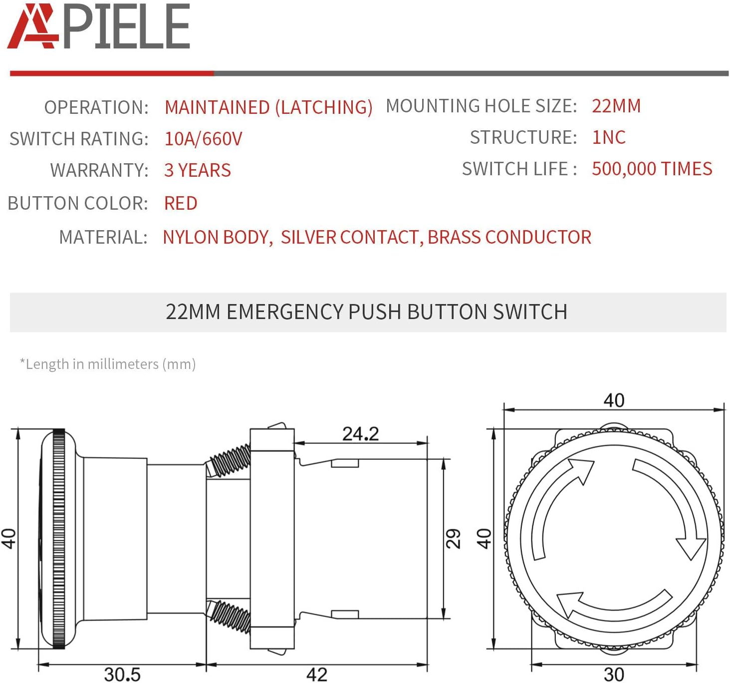
Image 1.1: Front view of the APIELE 22mm NC Red Mushroom Emergency Stop Push Button Switch.
Key Features:
- Button Type: Red Mushroom Head
- Contact Type: 1 Normally Closed (NC) silver contact
- Action: Latching (Push-Lock, Turn to Release)
- Mounting Hole Size: 22mm
- Voltage Rating: 600V
- Current Rating: 10 Amps
- Material: Plastic and Metal construction with silver contacts

Image 1.2: A selection of APIELE emergency stop push button switches, showcasing different styles.
2. Specifications
Detailed technical specifications for the XB2-01ZS Emergency Stop Push Button Switch are provided below:

Image 2.1: A table detailing the operating temperature, humidity, resistance, and mechanical/electrical life of the switch.
| Specification | Value |
|---|---|
| Operation Mode | Automatic, Push Button, Twist |
| Current Rating | 10 Amps |
| Operating Voltage | 600 Volts |
| Contact Type | Normally Closed (NC) |
| Connector Type | Screw |
| Terminal | Button |
| Circuit Type | 1-way |
| Mounting Type | Panel Mount |
| Actuator Type | Push Button Switch |
| Contact Material | Silver |
| International Protection Rating | IP54 |
| Number of Positions | 2 |
| Controller Type | Push Button |
| Control Method | Touch |
| Connectivity Protocol | X-10 |
| Color | Red (XB2-01ZS) |
| Unit Count | 1 Count |
| Item Weight | 3.2 ounces |
| Package Dimensions | 5.28 x 4.02 x 1.42 inches |
| Manufacturer | API Electric |

Image 2.2: Dimensional drawing of the 22mm emergency stop switch, showing key measurements in millimeters.
3. Installation
This section provides instructions for installing the APIELE XB2-01ZS Emergency Stop Push Button Switch. Ensure all power is disconnected before beginning installation.
3.1 Component Assembly
The switch consists of a contact base and an operation head (button). These components are designed for easy assembly and disassembly.

Image 3.1: Exploded view showing the contact base, operation head, and the fully assembled button.
- Disassembly: To remove the switch head from the contact base, turn the handle of the switch head counter-clockwise. This will detach the head from the base.
- Assembly: Align the switch head with the contact base and insert it. Turn the switch handle clockwise to lock the head securely onto the base.
The video below demonstrates the disassembly and assembly process for the emergency stop button switch.
Video 3.1: This video demonstrates how to disassemble and assemble the APIELE 22mm Emergency Stop Push Button Switch components.
3.2 Panel Mounting
The switch is designed for panel mounting with a 22mm diameter hole. Ensure the panel thickness is suitable (maximum 8.5mm / 0.3 inches).
- Drill a 22mm diameter hole in the desired mounting location on your control panel.
- Insert the switch head through the front of the panel.
- Secure the switch from the back of the panel using the provided locking nut and contact base.
3.3 Wiring Instructions
The XB2-01ZS switch features a Normally Closed (NC) contact. This means the circuit is closed (current flows) when the button is in its released state, and opens (current stops) when the button is pressed.
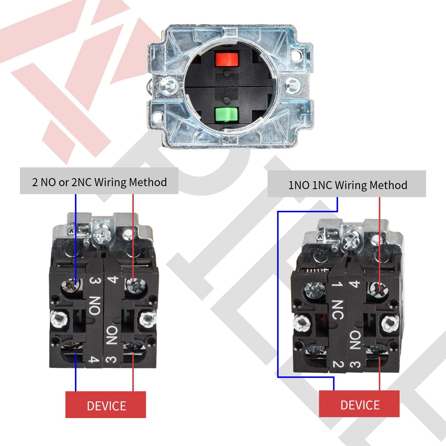
Image 3.2: Wiring diagrams illustrating connections for Normally Open (NO) and Normally Closed (NC) contacts. For this model (XB2-01ZS), refer to the NC contact diagram.
- Identify the NC terminals on the contact block. These are typically labeled.
- Connect the circuit wires to the screw terminals. Ensure connections are tight and secure to prevent electrical hazards.
- Verify the wiring against your system's electrical diagram.
4. Operation
The APIELE XB2-01ZS is an emergency stop switch designed for immediate cessation of machine operation in hazardous situations.
- To Activate (Stop): In an emergency, firmly press the red mushroom button. The button will latch into the depressed position, interrupting the circuit and stopping the connected device.
- To Deactivate (Release): To reset the switch and allow the device to operate again, turn the red mushroom button clockwise. The button will spring back to its original, released position, restoring the circuit.
The video below demonstrates the operational test of an emergency stop switch, showing how pressing the button stops a device and rotating it restarts the device.
Video 4.1: A real-world test demonstrating the push-to-stop and turn-to-release functionality of the emergency stop switch.

Image 4.1: Examples of typical applications for emergency stop switches, including control panels and machinery.
5. Maintenance
Regular inspection and basic maintenance can help ensure the longevity and reliable operation of your emergency stop switch.
- Visual Inspection: Periodically check the switch for any signs of physical damage, wear, or corrosion. Ensure the red mushroom head is intact and moves freely.
- Functionality Test: Regularly test the switch by pressing it to ensure it latches correctly and turning it to ensure it releases properly. Verify that the connected equipment responds as expected.
- Cleaning: Keep the switch clean and free from dust, dirt, or debris. Use a soft, dry cloth for cleaning. Avoid using harsh chemicals or abrasive materials.
- Connection Check: Ensure all wiring connections to the terminals remain tight and secure. Loose connections can lead to intermittent operation or electrical hazards.
6. Troubleshooting
If you encounter issues with your APIELE Emergency Stop Push Button Switch, consider the following troubleshooting steps:
- Switch Not Latching/Releasing:
- Ensure the switch head is correctly assembled and locked onto the contact base.
- Check for any obstructions preventing the button from fully depressing or rotating.
- Inspect for internal damage if the mechanism feels stiff or unresponsive.
- Device Not Stopping/Starting:
- Verify all wiring connections are secure and correctly terminated to the NC contacts.
- Check the continuity of the circuit with a multimeter when the switch is in both the pressed and released states.
- Ensure the connected device's power supply is active and functioning.
- Confirm that the switch's voltage and current ratings are appropriate for the application.
- Intermittent Operation:
- Inspect for loose wiring connections at the switch terminals or within the control panel.
- Check for signs of corrosion on the contacts.
If these steps do not resolve the issue, contact APIELE customer support for further assistance.
7. Warranty and Support
APIELE provides a warranty for this product:
- Warranty Period: 3 years from the date of purchase.
- Coverage: Replacement for non-man-made defects.
For warranty claims, technical support, or any questions regarding the APIELE XB2-01ZS Emergency Stop Push Button Switch, please contact APIELE customer service.
Manufacturer: API Electric


