1. Introduction
This manual provides essential information for the installation, operation, and maintenance of your WINBEST Oil Control Variable Valve Timing (VVT) Solenoid. Please read these instructions carefully before proceeding with installation or use to ensure proper function and longevity of the product.
2. Product Overview
The WINBEST Oil Control VVT Solenoid is a critical component in your vehicle's engine management system. It controls the oil flow to the variable valve timing system, which adjusts the camshaft position to optimize engine performance, fuel efficiency, and emissions across various RPMs and loads.

Image 2.1: Two WINBEST Oil Control VVT Solenoids. These solenoids are designed for precise control of oil flow within the engine's variable valve timing system.
Key Features:
- Direct replacement for OEM parts.
- Manufactured to meet or exceed OEM performance requirements.
- Constructed from durable Steel, Aluminum, and Plastic materials.
- Designed for reliable operation and effective oil flow control.
3. Vehicle Compatibility
This WINBEST Oil Control VVT Solenoid (Part Numbers: 917-199, 6M8Z-6M280-AA, 3M4Z6M280AA) is compatible with the following 2.5L L4 engine vehicles:
- Ford Escape: 2009-2015 (L4 152 2.5L / 2488CC) Exhaust, 2013-2014 (L4 152 2.5L / 2485CC) Exhaust
- Ford Fusion: 2010-2012 (L4 152 2.5L / 2488CC) Intake; Exhaust, 2011-2012 (L4 153 2.5L / 2500CC) Intake; Exhaust, 2010 (L4 153 2.5L / 2500CC) Intake; Exhaust
- Lincoln MKZ: 2011-2012 (L4 152 2.5L / 2488CC) Intake; Exhaust
- Mercury Mariner: 2009-2011 (L4 152 2.5L / 2488CC) Exhaust
- Mercury Milan: 2010-2011 (L4 152 2.5L / 2488CC) Intake; Exhaust
Note: Always verify compatibility with your specific vehicle's year, make, model, and engine size before purchasing and installing.
4. Installation Instructions
Installation of the VVT solenoid requires mechanical knowledge and appropriate tools. If you are not confident in performing this procedure, it is recommended to seek professional assistance.
4.1 Safety Precautions
- Ensure the vehicle's engine is cool before starting work.
- Disconnect the negative terminal of the battery to prevent electrical hazards.
- Wear appropriate personal protective equipment (PPE), including gloves and eye protection.
- Refer to your vehicle's specific service manual for detailed instructions and torque specifications.
4.2 General Installation Steps
- Locate the Solenoid: Identify the VVT solenoid(s) on your engine. Their location can vary depending on the vehicle model and whether it's an intake or exhaust solenoid.

Image 4.1: Accessing the engine compartment. Some VVT solenoids may require removal of engine covers for access.
- Disconnect Electrical Connector: Carefully disconnect the electrical connector from the old VVT solenoid.

Image 4.2: Disconnecting the electrical connector. Ensure the connector is fully disengaged before attempting to remove the solenoid.
- Remove Old Solenoid: Unscrew any retaining bolts or clips holding the solenoid in place. Gently pull the old solenoid out of its housing. Be prepared for a small amount of oil to drain.
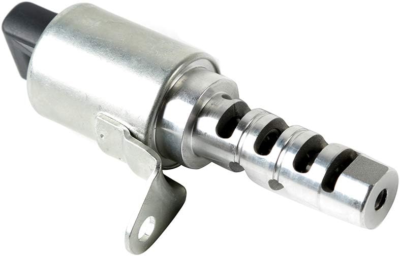
Image 4.3: A single WINBEST VVT Solenoid. Note the mounting bracket and electrical connector.
- Inspect and Clean: Inspect the solenoid bore for any debris or damage. Clean the area if necessary.
- Install New Solenoid: Apply a small amount of clean engine oil to the O-rings of the new WINBEST VVT solenoid. Carefully insert the new solenoid into the housing, ensuring it seats properly.

Image 4.4: Installing the new VVT solenoid. Ensure proper alignment and seating.
- Secure Solenoid: Reinstall any retaining bolts or clips, tightening them to the manufacturer's specified torque.

Image 4.5: VVT solenoid fully installed. The electrical connector is reattached.
- Reconnect Electrical Connector: Reconnect the electrical connector, ensuring it clicks into place securely.
- Reconnect Battery: Reconnect the negative terminal of the battery.
- Test Operation: Start the engine and check for any leaks or abnormal operation. The check engine light should extinguish if the solenoid was the cause of the fault.
5. Operation
The VVT solenoid operates by receiving electrical signals from the engine control unit (ECU). Based on these signals, the solenoid adjusts the oil pressure and flow to the camshaft phasers. This allows the engine to dynamically alter the timing of the intake and exhaust valves, optimizing engine performance for various driving conditions.

Image 5.1: Diagram of Variable Valve Timing. This illustration shows how the VVT system adjusts camshaft position to optimize valve timing.
Proper functioning of the VVT solenoid contributes to:
- Improved fuel efficiency.
- Increased engine power and torque.
- Reduced exhaust emissions.
- Smoother engine idle.
6. Maintenance
The VVT solenoid itself is generally a sealed unit and does not require routine maintenance. However, its longevity and performance are directly linked to the overall health of your engine and its lubrication system.
- Regular Oil Changes: Ensure you follow your vehicle manufacturer's recommended oil change intervals using the specified oil type. Dirty or low engine oil can significantly impact VVT solenoid operation and lifespan.
- Use Quality Oil Filters: A clean oil filter helps prevent contaminants from reaching and clogging the VVT solenoid's internal passages.
- Monitor Engine Lights: Pay attention to your vehicle's dashboard warning lights, especially the "Check Engine" light.

Image 6.1: Check Engine Light. An illuminated check engine light can indicate a VVT system issue.
7. Troubleshooting
If you experience issues after installing the VVT solenoid or suspect a VVT system problem, consider the following:
| Symptom | Possible Cause | Solution |
|---|---|---|
| Check Engine Light (CEL) illuminated | Faulty VVT solenoid, wiring issue, low/dirty engine oil, other engine sensor fault. | Scan for diagnostic trouble codes (DTCs). Check electrical connections. Verify engine oil level and condition. |
| Rough idle or stalling | Incorrect valve timing due to VVT solenoid malfunction. | Check VVT solenoid operation and electrical connections. Ensure proper oil pressure. |
| Reduced fuel economy | VVT system not optimizing valve timing. | Inspect VVT solenoid and related components. Ensure regular maintenance. |
| Decreased engine performance | Improper valve timing affecting power output. | Diagnose VVT system with a scan tool. Check for mechanical issues. |
If troubleshooting steps do not resolve the issue, it is recommended to consult a qualified automotive technician.
8. Specifications
- Brand: WINBEST
- Model Number: W-2*CVK6031
- OEM Part Numbers: 3M4Z6M280AA, 917-199, 6M8Z-6M280-AA
- Material: Steel/Aluminum/Plastic
- Exterior Finish: Steel/Aluminum/Plastic
- Inlet Connection Type: Electrical
- Outlet Connection Type: NPT
- Number of Ports: 2
- Specification Met: OEM
- Item Weight: 1.12 pounds
- UPC: 780682792393
9. Warranty and Support
WINBEST provides comprehensive quality assurance for its products. If you have any questions or encounter issues during the use or purchase process, please contact us via email. We are committed to assisting you and resolving any problems to the best of our ability.
For support, please refer to the contact information provided with your purchase or on the official WINBEST website.


