1. Introduction
This manual provides detailed instructions for the installation, operation, and maintenance of your FTSTech T22 125KHz Access Control System. This comprehensive kit is designed to enhance security for homes, offices, apartments, and factories by providing controlled access through a standalone keypad, electric strike lock, and RFID technology.
Please read this manual thoroughly before installation and operation to ensure correct usage and optimal performance.
2. Package Contents
The FTSTech T22 Access Control System package includes the following components:
- 1 x Access Control Keypad (T22)
- 1 x Power Supply Unit (3A)
- 1 x NC Electric Strike Lock
- 1 x Door Exit Button
- 10 x RFID Keyfobs (125KHz)
- 10 x RFID Cards (125KHz)
- 1 x User Manual (this document)

Image 2.1: All components included in the FTSTech T22 Access Control Kit. This image displays the keypad, power supply, electric strike lock, exit button, RFID keyfobs, and RFID cards.
3. Product Components Overview
3.1. Access Control Keypad (T22)
- Material: Plastic
- Voltage: 12V DC
- Current: 120mA
- User Capacity: 1000 users
- Proximity Reader Frequency: 125 KHz
- Compatible Cards: EM or EM compatible cards
- Reading Distance: 3-10 cm
- Open Modes: Card, Password, Card + Password
- Programming: Full programming from the keypad; no computer connection required.
- Dimensions: 117 x 75 x 22 mm

Image 3.1: The T22 Access Control Keypad, illustrating its support for 1000 users and three door open modes: RFID card, password, and a combination of RFID card and password.
3.2. Power Supply Unit (3A)
- AC Input: Standard AC100V-240V, 50-60Hz
- DC Output: Stabilized DC12V / 3A
- Material: Steel
- Protection: Automatic short-circuit protection (no voltage output in case of short circuit).
- Outputs: NC / NO outputs for various electric locks.
- Delay Adjustment: Supports 0-15 seconds delay adjustment.
- Dimensions: 140 x 67 x 33 mm (L/W/H)

Image 3.2: The 3A Power Supply Unit, detailing its input/output voltage, current, and dimensions.
3.3. NC Electric Strike Lock
- Material: Stainless Steel
- Operating Voltage: DC12V +/- 10%
- Working Current: 110mA-250mA
- Opening Mode: 90-degree swing door
- Secure Mode: NC model (Normally Closed) - Locked when powered ON, Unlocked when powered OFF.
- Compatibility: Particularly suitable for wooden doors.
- Dimensions: 150 x 28 mm
3.4. RFID Keyfobs and Cards
- Frequency: 125 KHz
- Chip: TK4100
- Type: Read-only
- Quantity: 10 Keyfobs, 10 Cards
- Keyfob Material: ABS
- Keyfob Color: Blue
- Keyfob Working Distance: 0-10 cm
- Keyfob Working Temperature: -25°C ~ +75°C
- Card Material: PVC
- Card Storage: 64bit
- Card Reading Time: 102ms
- Card Reading Times: 100,000 times
- Card Item Size: Approx 85 x 54 x 0.9 mm

Image 3.3: Detailed specifications for the included RFID Keyfobs and Cards, including material, frequency, and quantity.
4. Setup and Installation
Careful installation is crucial for the proper functioning of the access control system. Follow these steps for a successful setup.
4.1. Electric Strike Lock Installation
- Prepare Door Frame: Cut a hole in the door frame according to the dimensions of the electric strike lock. Ensure precise measurements for a secure fit.
- Assemble Lock: Insert the electric strike lock into the prepared opening in the door frame.
- Fix Strike Plate: Securely fix the strike plate to the door frame using appropriate screws.
- Test Fit: Ensure the door closes smoothly and the lock mechanism aligns correctly.
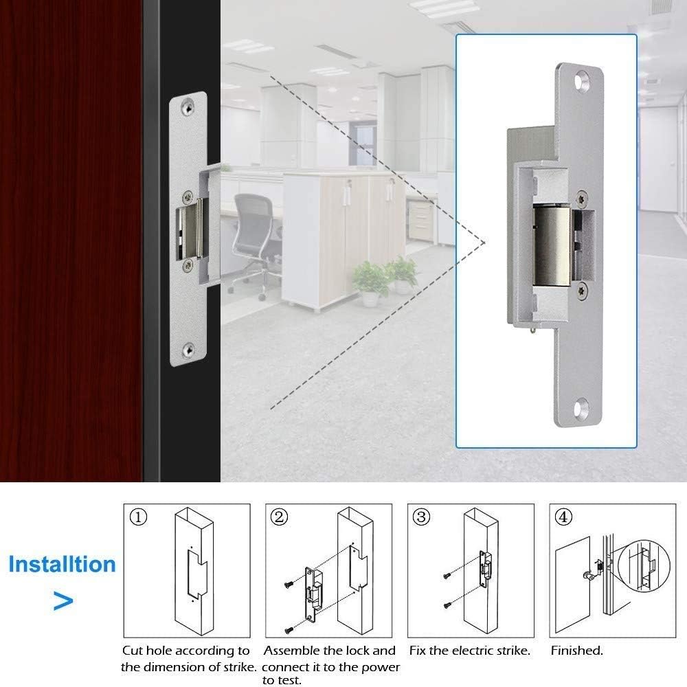
Image 4.1: Visual guide for installing the electric strike lock, showing the steps from cutting the hole to fixing the strike plate.
4.2. Component Placement
- Access Controller: Mount the access control keypad on the wall adjacent to the door, at a convenient height for users.
- Power Supply: Install the power supply unit in a secure, dry location, preferably near the access controller and the electric lock.
- Exit Button: Mount the exit button on the inside of the door, allowing for easy egress.
- Electric Strike Lock: As detailed above, install this into the door frame.
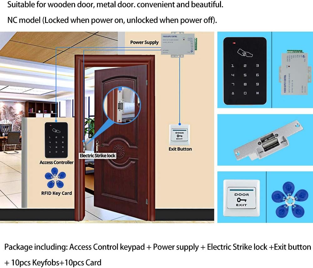
Image 4.2: An example of the access control system installed on a wooden door, showing the placement of the access controller, electric strike lock, power supply, and exit button.
5. Wiring Diagram
Follow the wiring diagram carefully to connect all components correctly. Incorrect wiring can damage the system or prevent it from functioning.

Image 5.1: Detailed wiring diagram showing connections between the power supply, electric strike lock, exit button, and access controller. Ensure all connections match this diagram.
Key Wiring Connections:
- Power Supply to Access Controller: Connect +12V and GND from the power supply to the corresponding terminals on the access controller.
- Power Supply to Electric Strike Lock (NC Mode): Connect the 'NC' terminal from the power supply to one wire of the electric strike lock, and the 'COM' terminal from the power supply to the other wire of the electric strike lock. (For NC lock, red wire to 'NC', black wire to 'COM' as per product description).
- Exit Button to Access Controller: Connect the exit button to the 'PUSH' and 'GND' terminals on the access controller.
- Power Supply AC Input: Connect the AC110-260V input to a suitable power source.
Important Note: The electric strike lock operates in NC (Normally Closed) mode. This means it is locked when power is supplied and unlocks when power is cut. Ensure your wiring reflects this behavior for safety and functionality.
6. Operating Instructions
The FTSTech T22 Access Control Keypad supports up to 1000 users and offers three modes for opening the door: RFID card, password, or a combination of card and password.
6.1. Initial Setup and Programming Mode
- Enter Programming Mode: Press * then enter the default master password (usually 123456), then press #. The indicator light will change, indicating you are in programming mode.
- Change Master Password (Recommended): In programming mode, press 0, then enter your new 6-digit master password, then press #. Confirm by re-entering the new password and pressing #.
6.2. Adding Users (RFID Cards/Keyfobs)
- Enter Programming Mode: (If not already) Press *, master password, #.
- Add Card: Press 1, then present the RFID card or keyfob to the keypad reader. The keypad will beep to confirm. You can add multiple cards consecutively.
- Exit Programming Mode: Press * to exit programming mode.
6.3. Adding Users (Passwords)
- Enter Programming Mode: Press *, master password, #.
- Add Password: Press 2, then enter a 4-6 digit user ID (e.g., 001), then press #. Then enter the 4-6 digit user password, then press #. Confirm by re-entering the password and pressing #.
- Exit Programming Mode: Press * to exit programming mode.
6.4. Deleting Users
- Enter Programming Mode: Press *, master password, #.
- Delete Card: Press 3, then present the RFID card or keyfob to be deleted to the keypad reader. The keypad will beep to confirm.
- Delete Password: Press 4, then enter the user ID of the password to be deleted, then press #.
- Exit Programming Mode: Press * to exit programming mode.
6.5. Opening the Door
- Using RFID Card/Keyfob: Present a programmed RFID card or keyfob to the keypad reader. The door will unlock briefly.
- Using Password: Enter your programmed user password, then press #. The door will unlock briefly.
- Using Card + Password: Present your programmed RFID card/keyfob, then enter your programmed user password, then press #. The door will unlock briefly.
- Using Exit Button: From the inside, press the door exit button. The door will unlock immediately.
7. Maintenance
To ensure the longevity and reliable operation of your FTSTech Access Control System, follow these maintenance guidelines:
- Regular Cleaning: Clean the keypad surface with a soft, dry cloth. Avoid abrasive cleaners or solvents that could damage the finish or electronics.
- Inspect Wiring: Periodically check all wiring connections for any signs of wear, corrosion, or loose connections. Ensure all wires are securely fastened.
- Power Supply Check: Verify that the power supply unit is free from dust and has adequate ventilation.
- Lock Mechanism: Ensure the electric strike lock mechanism is free of obstructions and operates smoothly. Lubricate moving parts if necessary with a non-greasy lubricant.
- RFID Cards/Keyfobs: Keep RFID cards and keyfobs clean and free from damage. Avoid bending or exposing them to extreme temperatures.
- Backup Power: If using an uninterruptible power supply (UPS) for backup, ensure it is functioning correctly and its batteries are charged.
8. Troubleshooting
If you encounter issues with your access control system, refer to the following troubleshooting guide:
| Problem | Possible Cause | Solution |
|---|---|---|
| Door does not unlock with card/password. |
|
|
| Keypad is unresponsive or no power indicator. |
|
|
| Door remains unlocked (NC lock). |
|
|
| Exit button does not work. |
|
|
9. Specifications
A summary of the technical specifications for the FTSTech T22 Access Control System components:
| Component | Specification |
|---|---|
| Access Control Keypad (T22) | Material: Plastic |
| Voltage: 12V DC | |
| Current: 120mA | |
| User Capacity: 1000 users | |
| Frequency: 125 KHz | |
| Reading Distance: 3-10 cm | |
| Dimensions: 117 x 75 x 22 mm | |
| Power Supply Unit (3A) | AC Input: 100V-240V, 50-60Hz |
| DC Output: 12V / 3A | |
| Material: Steel | |
| Delay Adjustment: 0-15 seconds | |
| Dimensions: 140 x 67 x 33 mm | |
| NC Electric Strike Lock | Material: Stainless Steel |
| Operating Voltage: 12V DC +/- 10% | |
| Working Current: 110mA-250mA | |
| Dimensions: 150 x 28 mm | |
| RFID Keyfobs & Cards | Frequency: 125 KHz |
| Chip: TK4100 | |
| Type: Read-only |
10. Warranty and Support
Warranty Information: Specific warranty details for this product are not provided in the available documentation. Please refer to your purchase receipt or contact the retailer for warranty terms and conditions.
Technical Support: For technical assistance, troubleshooting beyond this manual, or inquiries regarding replacement parts, please contact FTSTech customer support through the vendor's official channels or the platform where the product was purchased.


