1. Important Safety Information
Always prioritize safety when operating welding equipment. Failure to follow safety guidelines can result in serious injury or death.

Image Description: This image displays the rear panel of the PLASMARGON MIG255 welding machine, featuring prominent safety warning labels. These labels include warnings about electric shock, fire hazards, arc light emission, and the importance of reading the instruction manual. It also advises regular dusting of the machine.
- Electric Shock: Welding equipment can cause electric shock. Ensure proper grounding and insulation. Do not touch live electrical parts.
- Fire Hazard: Welding sparks can cause fires. Keep flammable materials away from the welding area. Have a fire extinguisher readily available.
- Arc Light Emission: Arc rays can injure eyes and burn skin. Always wear appropriate welding helmet, gloves, and protective clothing.
- Fumes and Gases: Welding produces fumes and gases that can be hazardous to your health. Work in a well-ventilated area.
- Read Manual: Always read and understand the entire instruction manual before operating the welding machine.
- Maintenance: Dust the machine at least twice a month to ensure proper operation and prevent overheating.
2. Product Overview
The PLASMARGON MIG255 is a versatile 3-in-1 welding machine designed for MIG, TIG (Lift TIG), and MMA (Stick) welding processes. It features dual voltage input (110V/220V) and is suitable for various welding applications on different metals.

Image Description: This image shows the PLASMARGON MIG255 welding machine from the front-right angle, with the MIG torch, electrode holder, and earth clamp connected. The digital display and control knobs are visible, indicating a ready-to-use setup.

Image Description: This image highlights several key features of the PLASMARGON MIG255 welder, including its capability for gasless welding, multi-process functionality (MIG/TIG/MMA), reduced spatter, portability for outdoor use, ease of operation, and stable arc initiation.
The machine is equipped with advanced inverter technology, providing stable arc performance and efficient power usage. It supports both gas and gasless welding for MIG, accommodating various wire types and diameters.
3. Package Contents
Upon unpacking, verify that all the following items are included in your package:
- PLASMARGON MIG255 Welder (x1)
- MIG Torch (2.7M / 8.2ft) (x1)
- TIG Torch (2.7M / 8.2ft) (x1)
- Electrode Holder (1.5M / 4.9ft) (x1)
- Earth Clamp (1.5M / 4.9ft) (x1)
- User Manual (x1)
- Note: Power plug is not included due to varying international standards.
4. Technical Specifications
Image Description: This image shows the PLASMARGON MIG255 welding machine alongside a detailed table of its technical specifications, including welding type, input voltage, frequency, duty cycle, efficiency, and various current ranges.
| Specification | Value |
|---|---|
| Model | MIG255 |
| Welding Type | TIG / MIG / MMA |
| Input Voltage | 110V / 220V ±15% |
| Frequency | 50Hz / 60Hz |
| Rated Output Capacity | 7.7 KV.A |
| Rated Input Current (A) | 35A |
| Output No-Load Voltage (V) | 69V |
| Rated Current Range (MIG) | 20 - 200A |
| Rated Current Range (MMA) | 20 - 180A |
| Rated Current Range (TIG) | 20 - 200A |
| Welding Wire Diameter | 0.8mm / 1.0mm / 1.2mm |
| Preflow Time of Gas (Freg) | 1 - 10s |
| Efficiency (η) | 85% |
| Rated Duty Cycle | 60% |
| Operation Mode (Trig) | 2T, 4T, S4T, Spot |
| Protection Class | IP21 |
| Insulation Class | F |
| Power Factor (COSφ) | 0.73 |
| Fuselage Material | Iron |
| Product Dimensions | 29.49 x 23.5 x 19.51 cm |
| Weight | 12.07 kg |
5. Setup
Before operating the welding machine, ensure it is properly set up according to these instructions.
Image Description: This image illustrates the PLASMARGON MIG255 welding machine with its various components, including the MIG torch, electrode holder, and earth clamp, all connected to their respective ports on the front panel. This provides a visual guide for initial setup.
- Power Connection: Connect the welding machine to a suitable 110V or 220V power supply. The machine automatically detects the input voltage. Ensure the power source can handle the rated input current of 35A.
- Earth Clamp Connection: Connect the earth clamp cable to the negative (-) terminal on the front panel. Attach the clamp securely to the workpiece or welding table, ensuring good electrical contact.
- MIG Torch Connection: For MIG welding, connect the MIG torch cable to the designated MIG connector on the front panel. Ensure it is securely fastened.
- TIG Torch Connection: For TIG welding, connect the TIG torch cable to the designated TIG connector. Connect the gas hose from the TIG torch to your gas regulator if using shielding gas.
- Electrode Holder Connection: For MMA (Stick) welding, connect the electrode holder cable to the positive (+) terminal on the front panel.
- Wire Feed Setup (MIG): Open the wire feed compartment. Install the appropriate welding wire (0.8mm, 1.0mm, or 1.2mm) onto the spool holder. Thread the wire through the feed rollers and into the MIG torch liner. Adjust the tension of the feed rollers.
- Gas Connection (MIG/TIG): If performing gas-shielded MIG or TIG welding, connect your shielding gas cylinder regulator to the gas inlet on the rear of the machine. Ensure all connections are leak-free.
6. Operating Instructions
The PLASMARGON MIG255 offers MIG, TIG, and MMA welding modes. Select the appropriate mode and adjust parameters for your specific welding task.
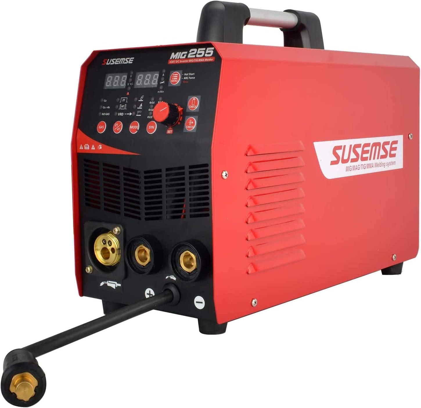
Image Description: This image provides a close-up view of the front control panel of the PLASMARGON MIG255 welding machine. It shows the digital display, mode selection buttons (MIG, TIG, MMA), voltage/current adjustment knob, and indicators for gas/gasless operation and wire diameter settings.
6.1 General Operation Steps
- Power On: Turn on the main power switch located on the rear of the machine.
- Select Mode: Use the "MODE" button on the front panel to select MIG, TIG, or MMA welding.
- Adjust Parameters: Use the control knob to adjust welding current (Amperage) and voltage (for MIG). Refer to welding charts for recommended settings based on material thickness and type.
- Start Welding: Initiate the arc according to the selected welding process.
6.2 MIG Welding (Gas / Gasless)
- Gas-Shielded MIG: Use solid wire (0.8mm, 1.0mm, 1.2mm) with appropriate shielding gas (e.g., CO2 or Argon/CO2 mix). Ensure gas flow is set correctly.
- Gasless MIG: Use flux-cored wire (0.8mm, 1.0mm, 1.2mm). No external shielding gas is required as the flux core produces its own shielding.
- Wire Feed Speed: Adjust wire feed speed in conjunction with voltage for optimal arc stability and bead appearance.
- Operation Modes: Select 2T (two-stroke) for basic trigger control or 4T (four-stroke) for continuous welding without holding the trigger. S4T and Spot modes are also available for specialized applications.
6.3 TIG Welding (Lift TIG)
- Electrode: Use a tungsten electrode of appropriate size and type for your material.
- Shielding Gas: Argon gas is typically used for TIG welding. Ensure gas flow is set.
- Lift Arc Ignition: Touch the tungsten electrode to the workpiece, then lift it slightly to initiate the arc. This method minimizes tungsten contamination.
- Preflow Time: Adjust the gas preflow time (1-10s) to ensure adequate shielding before arc ignition.
6.4 MMA (Stick) Welding
- Electrode Selection: Choose the correct type and diameter of welding electrode for your material and application.
- Current Adjustment: Adjust the welding current (Amperage) based on the electrode size and material thickness.
- Arc Ignition: Strike the electrode against the workpiece to initiate the arc. Maintain a consistent arc length.
7. Maintenance
Regular maintenance ensures the longevity and optimal performance of your welding machine.
- Cleaning: Dust the machine's interior and exterior at least twice a month. Use compressed air to remove dust and debris from cooling vents and internal components.
- Cable Inspection: Regularly inspect all welding cables, torches, and clamps for damage, fraying, or loose connections. Replace damaged components immediately.
- Wire Feed System: Clean the wire feed rollers and liner periodically to prevent wire feeding issues. Ensure the wire spool rotates freely.
- Storage: Store the welding machine in a clean, dry environment, away from excessive dust, moisture, and corrosive materials.
8. Troubleshooting
This section provides general guidance for common issues. For complex problems, contact customer support.
- No Power:
- Check power cord connection and wall outlet.
- Verify circuit breaker or fuse is not tripped.
- Ensure the main power switch on the machine is ON.
- Poor Arc Start/Unstable Arc:
- Ensure earth clamp has good contact with the workpiece.
- Check welding parameters (current, voltage, wire feed speed) are set correctly for the material and process.
- Inspect welding consumables (MIG tips, TIG tungsten, MMA electrodes) for wear or damage.
- For gas-shielded processes, verify gas flow and connections.
- Wire Feeding Issues (MIG):
- Check wire spool for tangles or binding.
- Ensure wire feed rollers are clean and tensioned correctly.
- Inspect MIG torch liner for blockages or damage.
- Verify correct wire diameter is selected on the machine.
- Overheating:
- Allow the machine to cool down if the thermal overload indicator activates.
- Ensure cooling vents are not obstructed.
- Check if the duty cycle is being exceeded.
9. Warranty and Support
PLASMARGON is committed to customer satisfaction. For any defective item or technical assistance, please contact our customer service department.
Please refer to your purchase documentation or the manufacturer's official website for specific warranty terms and contact information.