Introduction
This user manual provides detailed instructions for the ATNSINC 433MHz RF Wireless Transmitter and Receiver Module Kit. This kit is designed for wireless communication in various applications, including remote control systems, home automation, and DIY electronics projects. It allows for the transmission and reception of data over radio frequency at 433MHz.
Safety Information
For optimal performance and safety, please observe the following guidelines:
- Keep the modules away from signal interference sources.
- Avoid placing the modules near high-tension power wires.
- Ensure the VCC voltage supplied to the modules is consistent with their specified working voltage.
- Proper power filtering is recommended for stable operation.
Product Overview
The kit includes both transmitter and receiver modules, designed for simple integration into your projects.

Figure 1: Overview of the 433MHz RF Wireless Transmitter and Receiver Module Kit.
Transmitter Module (Square Shape)
- Allows wireless communication with RF controlled devices.
- Operates at 433MHz.
- Pinout: DATA, VCC, GND.
Receiver Module (Rectangle Shape)
- Receives signals from compatible 433MHz transmitters.
- Pinout: DATA, VCC, GND.

Figure 2: Identification of Transmitter and Receiver Modules with their respective pinouts.
Specifications
| Feature | Transmitter Module | Receiver Module |
|---|---|---|
| Operating Voltage | 3.5-12V DC | 5V DC |
| Static Current | N/A | 4mA |
| Receive Sensitivity | N/A | -105dB |
| Transmission Frequency | 433.92MHz | 433MHz |
| Transmitting Power | 10mW | N/A |
| AM Transfer Rate | 4KB/s | N/A |
| Modulation Type | ASK or OOK | N/A |
| Transfer Rate | <10Kbps | N/A |
| Working Method | AM | N/A |
| Antenna (External) | 25cm single core wire, coiled into a spiral | 32cm single core wire, coiled in helix |
| Dimensions (L x W x H) | 19mm x 18.9mm | 30mm x 13.5mm x 7mm |

Figure 3: Detailed dimensions for the Transmitter and Receiver Modules.
Setup and Wiring
Proper wiring and antenna setup are crucial for reliable communication.
Antenna Connection
The antenna significantly impacts the module's performance. It is recommended to connect an antenna with a 1/4 wavelength. For 433MHz, a 17cm (approximately 6.7 inches) single-core wire (e.g., 50 ohm) is suitable. The antenna should be as straight as possible and kept away from shielding, high voltage, and interference sources.
Note: Antennas are not included in the kit and must be provided by the user.
Module Pinout and Connections
Refer to the diagram below for correct pin connections for both the transmitter and receiver modules.
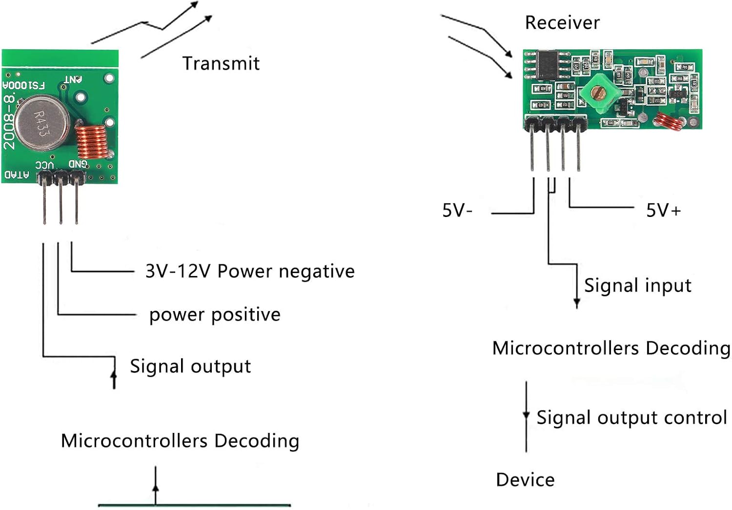
Figure 4: Wiring diagram illustrating connections for the Transmitter and Receiver Modules to a microcontroller.
- Transmitter Module Pinout (from left to right, looking at the top of the board):
- DATA: Signal Output (Connect to microcontroller's data output)
- VCC: Power Positive (Connect to 3.5-12V DC power supply)
- GND: Ground (Connect to common ground)
- Receiver Module Pinout (from left to right, looking at the top of the board):
- GND: Ground (Connect to common ground)
- VCC: Power Positive (Connect to 5V DC power supply)
- Signal Input: Data Output (Connect to microcontroller's data input)
Operating Instructions
Once wired correctly, these modules can be used for various wireless communication tasks. They operate using Amplitude Modulation (AM) or On-Off Keying (OOK) for data transfer.
- Power On: Apply the specified operating voltage to both the transmitter and receiver modules.
- Data Transmission:
- Connect the DATA pin of the transmitter to a digital output pin of your microcontroller (e.g., Arduino, Raspberry Pi).
- Send digital signals (e.g., HIGH/LOW pulses) from your microcontroller to the transmitter's DATA pin.
- The transmitter will convert these signals into 433MHz RF waves.
- Data Reception:
- Connect the Signal Input pin of the receiver to a digital input pin of your microcontroller.
- The receiver will detect 433MHz RF signals and convert them back into digital signals on its Signal Input pin.
- Your microcontroller can then read these signals to interpret the transmitted data.
- Matching Parameters: Ensure that the transmitting frequency, decoding mode, and oscillating resistance of your setup match between the transmitter and receiver for successful communication.
These modules are commonly used with microcontrollers for encoding and decoding data, enabling applications like remote control switches, home automation, and security systems.
Maintenance
The 433MHz RF Wireless Transmitter and Receiver Modules are low-maintenance components. Follow these general guidelines to ensure longevity:
- Keep the modules clean and free from dust and debris.
- Store in a dry environment to prevent moisture damage.
- Avoid exposing the modules to extreme temperatures or direct sunlight.
- Handle with care to prevent physical damage to the pins or components.
Troubleshooting
If you encounter issues with your 433MHz RF modules, consider the following common problems and solutions:
| Problem | Possible Cause / Solution |
|---|---|
| No communication or very short range |
|
| Erratic or unreliable data reception |
|
| Module not powering on |
|
Warranty and Support
This product is covered by a standard manufacturer's warranty. For specific warranty details or technical support, please contact ATNSINC customer service through the retailer where the product was purchased.
For additional resources and community support, consider searching online forums and communities dedicated to Arduino, Raspberry Pi, and RF electronics, as these modules are widely used in such projects.


