1. Product Overview
The DALY Smart BMS (Battery Management System) is designed for LiFePo4 24V 60A 8S battery packs, offering advanced protection and monitoring capabilities. It ensures optimal performance and extends the lifespan of your lithium battery system.
Key Features:
- Comprehensive protection: Overcurrent, Overcharge, Overdischarge, Short circuit, and Temperature protection.
- Enhanced durability: Double protection via injection patent technology and patent shell, offering waterproof, dustproof, shockproof, and anti-static properties.
- Smart monitoring: Check battery status and modify parameters in real-time via Bluetooth app or PC software.
- Versatile communication: Supports BT, UART, RS485, and CAN communication protocols.
- Quality assurance: ISO/FCC/RoHS/PSE/CE approved.

Figure 1: DALY Smart BMS LiFePo4 24V 60A 8S unit.

Figure 2: Side view of the DALY Smart BMS, highlighting connection ports.

Figure 3: Illustration of UART and Bluetooth communication interfaces for the BMS.
2. Specifications
| Specification | Value |
|---|---|
| Product Type | LiFePO4 8S 60A Common Port with Balance |
| Communication | UART |
| Discharge Current | 60A |
| Over-discharge Current | 90A |
| Charge Current | 30A |
| Overcharge Current | 90A |
| Overcharge Voltage | 3.75V±0.05V (any string) |
| Over-discharge Voltage | 2.2V±0.05V (any string) |
| Charge Voltage | S*3.65V |
| Size | 66*128*18mm |
| Output Wire | 10AWG / 130mm |
| Balance Wires | 24AWG / 450mm |

Figure 4: Detailed specifications for the DALY Smart BMS.
3. Setup and Wiring
3.1 Packing List
Ensure all components are present before beginning installation:
- 3.2V Lifepo4 BMS x 1
- Bluetooth Module x 1
- NTC sensor x 1
- Sampling cable x 1
- UART cable x 1
- Instruction Manual x 1

Figure 5: Contents of the DALY Smart BMS package.
3.2 Required Tools
For proper installation, you will need:
- Soldering machine (recommended temperature: 662°F/350°C; for novices, 350°F/177°C)
- Ceramic scissors (insulated, for cutting wires)
- Double-sided tape
- Tin wire
- Multimeter
- Detection board (for verifying wiring)
3.3 Wiring Procedure
Follow these steps carefully to connect the BMS to your battery pack:
- Prepare Materials: Gather all necessary tools and components. Ensure your battery cells are properly arranged and ready for connection.
- Determine Sampling Points: Identify the correct sampling points on your battery pack. The first sampling point is the total negative electrode (B-). Subsequent points are between the negative of one cell and the positive of the next (B1, B2, etc.), up to the total positive electrode (B+).
- Test Wiring Correctness: Before connecting the BMS, verify the wiring of your battery pack. You can use a detection board or a multimeter to check the voltage between adjacent wires. Ensure all lights on the detection board illuminate, or that the multimeter shows consistent voltage increments (approximately 3.45V per cell for LiFePo4) as you move across the sampling points. If the wiring is incorrect, the lights will not turn on, or the voltage readings will be irregular.
- Secure Wiring: Fix the balance wires to the battery pack using double-sided tape to prevent movement and ensure stable connections.
- Solder Balance Wires: Carefully solder each balance wire to its corresponding sampling point on the battery pack. The black wire connects to B- (total negative), the first red wire to B1, the second red wire to B2, and so on, with the last red wire connecting to B+ (total positive). Ensure clean and secure solder joints.
- Connect BMS: Once all balance wires are soldered and secured, connect the sampling cable to the BMS. Important: Do not insert the BMS into the battery pack until all wiring is complete and verified.

Figure 6: General wiring diagram for the DALY Smart BMS with a battery pack.
3.4 Wiring Tutorial Videos:
Video: Prepare Materials for BMS Wiring
Description: This video demonstrates the essential tools and materials required before starting the DALY Smart BMS wiring process.
Video: Checking Battery Cell Voltage Before BMS Connection
Description: Learn how to properly test each battery cell's voltage using a multimeter to ensure correct wiring before connecting to the BMS.
Video: Sampling Point Determination for BMS Wiring
Description: This video guides you through identifying and marking the correct sampling points on your battery pack for accurate BMS connection.
Video: Soldering Balance Wires to Battery Pack
Description: A step-by-step tutorial on how to properly solder the balance wires to the battery pack, ensuring secure and reliable connections.
4. Operating the Smart BMS
The DALY Smart BMS offers convenient monitoring and parameter adjustment via a dedicated mobile application or PC software.
4.1 Bluetooth App Connection
Connect your smartphone to the BMS via the Bluetooth module to access real-time battery data and settings.
- Download the DALY Smart BMS app (available for Android and iOS).
- Ensure the Bluetooth module is connected to the BMS.
- Open the app and search for your BMS device.
- Once connected, you can view cell voltage, total voltage, temperature, State of Charge (SOC), charge/discharge cycles, and other parameters.
- Parameters can be freely checked and set within the app.
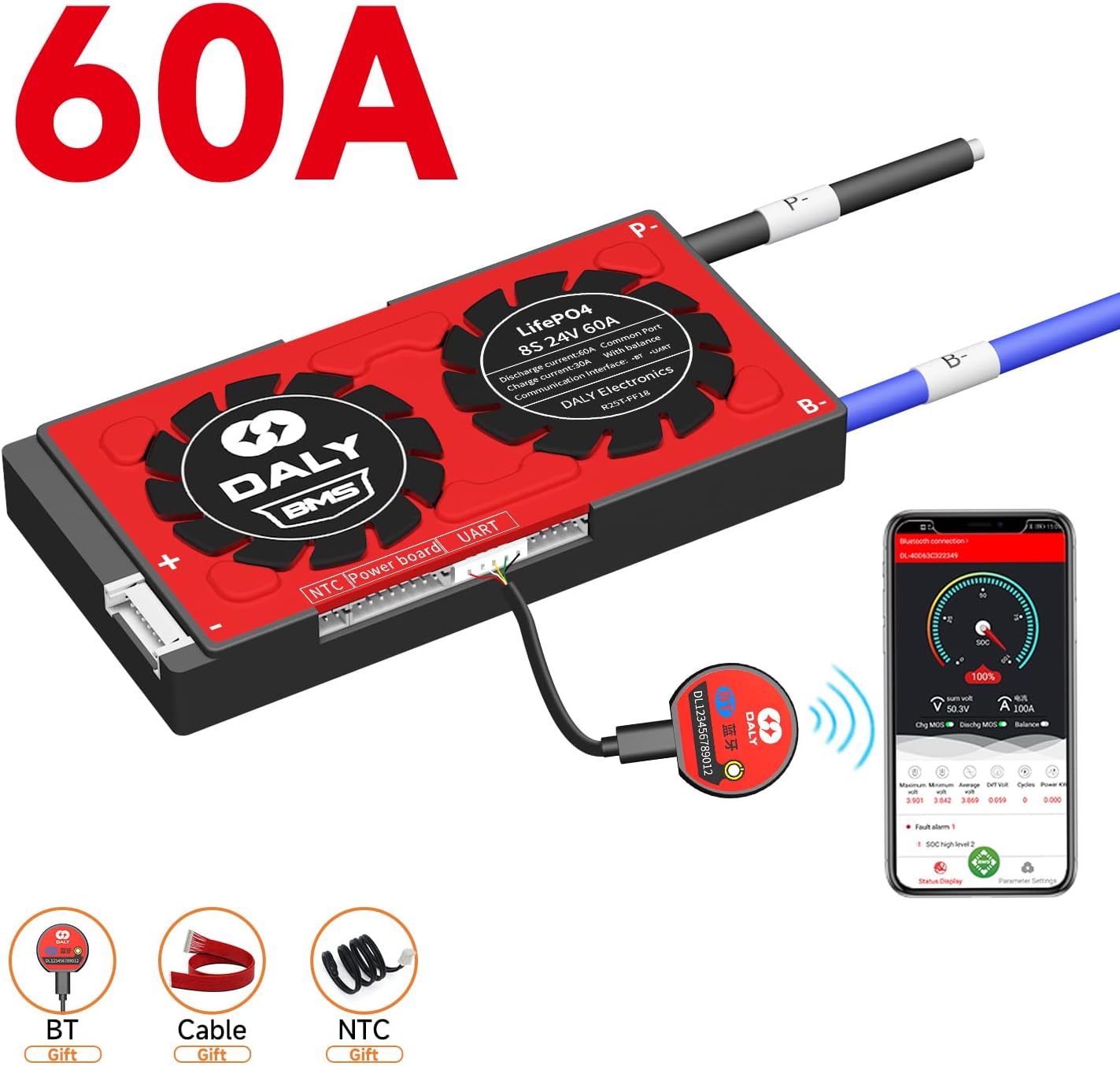
Figure 7: DALY Smart BMS connected to a smartphone app via Bluetooth for real-time monitoring.
4.2 PC Software Connection (UART/RS485/CAN)
For more detailed analysis and advanced settings, connect the BMS to a PC using the UART, RS485, or CAN communication interfaces.
- Install the DALY BMS PC software.
- Connect the appropriate communication cable (UART, RS485, or CAN) from the BMS to your PC.
- The software provides a comprehensive display of battery data and allows for in-depth parameter configuration.
Video: DALY Smart BMS Overview and Features
Description: This video provides a general overview of the DALY Smart BMS, its features, and various application scenarios, including app and PC monitoring.
5. Maintenance
Regular maintenance ensures the longevity and reliable operation of your DALY Smart BMS:
- Visual Inspection: Periodically check all wiring and connections for any signs of damage, corrosion, or loose contacts.
- Cleaning: Keep the BMS unit clean and free from dust and debris. Use a soft, dry cloth for cleaning. Avoid using liquids or abrasive cleaners.
- Environmental Conditions: Ensure the BMS operates within its specified temperature and humidity ranges to prevent damage. Provide adequate ventilation if installed in an enclosed space.
- Software Updates: Check for and install any available firmware or software updates for the BMS app or PC software to ensure optimal performance and access to new features.
6. Troubleshooting
If you encounter issues with your DALY Smart BMS, consider the following troubleshooting steps:
- No Power/No Indication: Verify all power connections to the BMS and battery pack. Check the main fuse if applicable.
- Communication Issues: Ensure the Bluetooth module or communication cables (UART/RS485/CAN) are securely connected. Restart the app or PC software. Check your device's Bluetooth settings.
- Abnormal Voltage/Current Readings: Re-check all balance wire connections to ensure they are correctly soldered and making good contact with the battery cells. Use a multimeter to verify individual cell voltages.
- Protection Triggered: If the BMS enters a protection state (e.g., overcharge, overdischarge, overcurrent), identify the cause. This may require checking battery cell health, load conditions, or charging parameters. The app/PC software can provide diagnostic information.
- Unusual Heating: Disconnect the battery pack from the load and charger immediately. Inspect for short circuits or damaged components.
If the problem persists after basic troubleshooting, contact DALY customer support for assistance.
7. Warranty and Support
DALY provides comprehensive customer support for its products:
- Technical Support: Lifetime technical support is available for all DALY BMS products.
- Customer Service: 24-hour one-on-one customer service is provided to address any queries or issues you may have.
- Contact: For further assistance, please refer to the contact information provided in your product packaging or visit the official DALY website.


