Introduction
This manual provides comprehensive instructions for the installation, operation, and maintenance of your iluminize Dimm-Aktor 500.201. This compact dimmer actuator is designed to control 230V dimmable lights, offering flexible control options via radio frequency (RF) remote controls, a WiFi Bridge for smartphone integration, or traditional push-button switches. Please read this manual thoroughly before installation and use to ensure safe and correct operation.
Safety Information
WARNING: Installation of this device involves high voltage (230V). To prevent electric shock or damage to the device, installation must be performed by a qualified electrician in accordance with local electrical codes and regulations.
- Always disconnect power at the main circuit breaker before performing any installation or maintenance.
- This device is designed for indoor use only. Do not expose it to moisture or extreme temperatures.
- Ensure that the total load of connected lamps does not exceed the maximum rated power of 400W.
- Use only with dimmable lamps and luminaires.
Product Overview
The iluminize Dimm-Aktor 500.201 is a compact dimmer actuator designed for seamless integration into existing electrical systems. Its small form factor allows it to be installed discreetly behind standard wall switches or in ceiling fixtures.

Front view of the iluminize Dimm-Aktor 500.201, showing connection terminals for L (Live), N (Neutral), and output to the lamp, along with 'Min.Set' and 'Learning Key' buttons. Input voltage range is AC 100-240V, max 400W.

Side view of the iluminize Dimm-Aktor 500.201, highlighting its compact design suitable for installation in switch boxes.
The Dimm-Aktor is compatible with various iluminize remote controls and the iluminize WiFi Bridge, allowing for versatile control options.

Diagram illustrating the iluminize Dimm-Aktor 500.201's compatibility with various iluminize remote controls, wall dimmers, and the WiFi Bridge for smartphone control.
Setup and Installation
As previously stated, installation must be carried out by a qualified electrician. Ensure power is disconnected before proceeding.
Wiring Diagram
Follow the wiring diagram below for correct connection of the Dimm-Aktor to your electrical system and lighting fixture. The device requires both Live (L) and Neutral (N) connections.

Detailed wiring diagram for the iluminize Dimm-Aktor 500.201, showing connections for Live (L), Neutral (N), and the dimmable lamp. It also illustrates an optional connection for a push-button switch (Taster Lichtschalter) for local control.
- Power Disconnection: Turn off the main power supply at the circuit breaker before starting any wiring.
- Connect Lamp: Connect the dimmable lamp or luminaire to the output terminals of the Dimm-Aktor (marked with a lamp symbol and 'L').
- Connect Power Input: Connect the main Live (L) and Neutral (N) wires from your electrical supply to the corresponding input terminals on the Dimm-Aktor (marked 'L' and 'N' under 'AC 100-240V INPUT').
- Optional Push-Button Switch: For local control, connect a push-button switch to terminals A1 and A2. The voltage range for this connection is 8-230V.
- Secure Connections: Ensure all wire connections are secure and properly insulated.
- Restore Power: Once all connections are verified, restore power at the circuit breaker.
Physical Installation
The compact dimensions of the Dimm-Aktor (45 mm x 45 mm x 21 mm) allow it to be installed in standard deep switch boxes (minimum 60mm depth recommended) or within ceiling voids. Ensure adequate ventilation and avoid enclosing the device in excessively tight spaces.
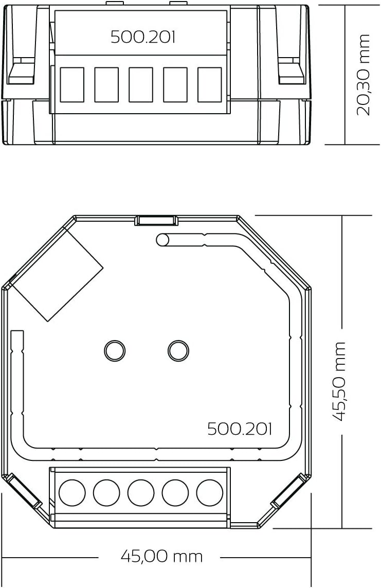
Technical drawing showing the precise dimensions of the iluminize Dimm-Aktor 500.201: 45.50 mm x 45.00 mm x 20.30 mm, indicating its compact size for installation.
Operating Instructions
Pairing with a Remote Control
To link your Dimm-Aktor with an iluminize remote control, follow these steps:
- Power On: Ensure the Dimm-Aktor is connected to power and the connected lamp is illuminated (approximately 75% brightness).
- Activate Remote: If necessary, power on your iluminize remote control.
- Select Zone (if applicable): On multi-zone remotes, select the desired zone (1-6) you wish to pair with the Dimm-Aktor.
- Initiate Pairing: Briefly press the 'Learning Key' button on the Dimm-Aktor. The Dimm-Aktor will enter pairing mode for 15 seconds.
- Confirm Pairing: Within the 15-second pairing window, use the remote control to perform a dimming or on/off action. The connected lamp will flash briefly to confirm successful pairing.

Illustration showing how to power on the remote control by pressing the power button, indicated by a red status indicator.

Image demonstrating how to select a zone (e.g., zone 2) on a multi-zone remote control for pairing with the Dimm-Aktor.

Visual guide showing a finger pressing the 'Learning Key' button on the iluminize Dimm-Aktor 500.201 to initiate the pairing process with a remote control.
Setting Minimum Brightness
To prevent flickering at very low dimming levels, you can set a minimum brightness for your connected lamps:
- Dim Down: Using your paired remote control, dim the lights down until the connected lamp begins to flicker.
- Adjust Up: Slowly dim the lights slightly brighter until the flickering stops.
- Set Minimum: Briefly press the 'Min.Set' button on the Dimm-Aktor. The connected lamp will flash to confirm the new minimum brightness setting.

Diagram illustrating the process of setting the minimum brightness on the iluminize Dimm-Aktor 500.201 by pressing the 'Min.Set' button after adjusting the light level with a remote to prevent flickering.
Resetting Pairing and Minimum Brightness
To clear all paired remote controls and reset the minimum brightness setting to default, press and hold the 'Learning Key' button on the Dimm-Aktor for several seconds until the connected lamps flash. This indicates a successful reset.
Maintenance
The iluminize Dimm-Aktor 500.201 requires minimal maintenance. Ensure the device remains free from dust and debris. Clean the exterior with a dry, soft cloth. Do not use liquid cleaners or abrasive materials. There are no user-serviceable parts inside the device. Any repairs should be conducted by qualified personnel only.
Troubleshooting
- Lamp not responding (no on/off or dimming):
- Check all wiring connections for proper installation and security.
- Verify that the main power supply is active.
- Ensure the remote control has working batteries and is within range.
- Re-attempt the pairing process between the Dimm-Aktor and the remote control.
- Lamp flickers at low brightness:
- Adjust the minimum brightness setting as described in the 'Setting Minimum Brightness' section.
- Ensure the connected lamp is explicitly rated as dimmable.
- Remote control not responding:
- Check the remote control's battery and replace if necessary.
- Ensure the remote is paired correctly with the Dimm-Aktor. If unsure, perform the pairing process again.
- Device completely unresponsive:
- Turn off power to the Dimm-Aktor at the circuit breaker for a few minutes, then restore power (power cycle).
- If the issue persists, contact a qualified electrician for inspection. Do not attempt to open or repair the device yourself.
Specifications
| Brand | iluminize |
| Model Number | 500.201 |
| Dimensions (L x W x H) | 4.5 x 4.5 x 2.1 cm |
| Weight | 40 g |
| Input Voltage | AC 100-240 Volts |
| Max. Output Power | 400 Watts |
| Control Type | Radio (RF), WiFi (with optional Bridge), Push-button |
| Dimming Technology | Phase-cut dimming |
| Material | Plastic |
| Installation Type | Wall mount (behind switch) |
| Usage Environment | Indoor only |
| Special Features | Dimmability, remote control compatibility, multi-zone control, adjustable minimum brightness |
Warranty and Support
For warranty information, technical support, or further inquiries regarding your iluminize Dimm-Aktor 500.201, please contact iluminize customer service directly or visit their official website. Keep your proof of purchase for warranty claims.
Official Website: iluminize.com


