
1. Introduction
The AOPUTTRIVER AP-770HC is a 6000-count True RMS digital multimeter designed for accurate and reliable electrical measurements. It features auto-ranging capabilities and a variety of functions including voltage, current, resistance, capacitance, frequency, temperature, and Non-Contact Voltage (NCV) detection. This manual provides essential information for the safe and proper use of your multimeter.
2. Safety Information
Please read all safety warnings and operating instructions carefully before using this instrument. Failure to comply with safety precautions may result in electric shock, fire, or damage to the meter.
- Always ensure the test leads are properly connected and the function switch is set to the correct range before making any measurements.
- Do not measure voltage exceeding 1000V DC or 750V AC.
- Exercise extreme caution when working with live circuits. Avoid contact with bare wires or terminals.
- Never measure current on a circuit with voltage present without first disconnecting power and inserting the meter in series.
- Do not use the meter if it appears damaged or if the test leads are compromised.
- Replace the battery when the low battery indicator appears to ensure accurate readings.
- Adhere to local and national safety codes.
3. Package Contents
Verify that all items listed below are present in your package:
- 1 x AOPUTTRIVER AP-770HC Multimeter
- 2 x Test Leads (Red and Black)
- 1 x Carrying Bag
- 1 x 9V (6F22) Battery
- 1 x Small Screwdriver
- 1 x Temperature Probe
- 1 x User Manual (English)

Image: The package contents, including the multimeter, test leads, carrying bag, battery, screwdriver, temperature probe, and user manual.
4. Product Overview
4.1 Front Panel Layout
Familiarize yourself with the various components of the multimeter's front panel:
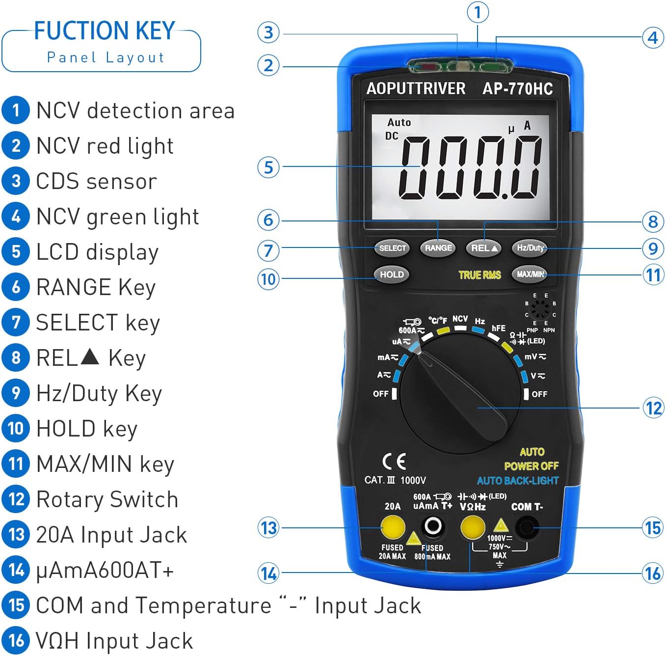
Image: A detailed view of the multimeter's front panel, highlighting key functional areas and buttons.
- NCV Detection Area
- NCV Red Light Indicator
- CDS Sensor (for Auto Backlight)
- NCV Green Light Indicator
- LCD Display
- RANGE Key
- SELECT Key
- REL▲ Key (Relative Value)
- Hz/Duty Key
- HOLD Key
- MAX/MIN Key
- Rotary Switch
- 20A Input Jack
- μA/mA/600AT+ Input Jack
- COM and Temperature "-" Input Jack
- VΩHz Input Jack
4.2 Physical Features
The AP-770HC is designed for durability and ease of use:
- Double Protection: The meter is encased in a protective rubber boot for enhanced durability against drops and impacts.
- Integrated Kickstand: A built-in stand allows the meter to be propped up for hands-free viewing, rotating 180 degrees for optimal angle.
- Mechanical Blocking System: This safety feature prevents incorrect lead insertion by physically blocking unused input jacks based on the rotary switch position.
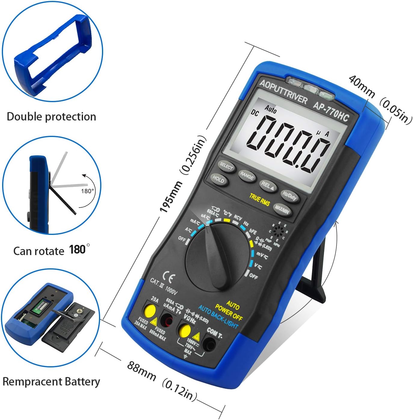
Image: Illustrations of the multimeter's physical attributes, including its dimensions, protective casing, and battery access.
5. Setup
5.1 Battery Installation
The AP-770HC requires one 9V (6F22) battery for operation. To install or replace the battery:
- Ensure the multimeter is turned OFF.
- Locate the battery compartment cover on the back of the meter.
- Use the provided small screwdriver to loosen the screw securing the battery cover.
- Remove the cover and connect the 9V battery to the battery clip, observing correct polarity.
- Place the battery into the compartment and replace the cover, securing it with the screw.
6. Operating Instructions
6.1 General Operation
To begin using the multimeter:
- Insert the test leads into the appropriate input jacks. The black lead typically connects to the COM jack. The red lead connects to the VΩHz jack for voltage, resistance, and other measurements, or to the μA/mA or 20A jack for current measurements.
- Rotate the function switch to the desired measurement mode. The mechanical blocking system will guide you to the correct input jacks for the selected function.
- The meter will automatically select the appropriate range (auto-ranging). For some functions, you can press the RANGE button to manually select a range.
6.2 Measurement Functions
Below are instructions for common measurement types:
DC Voltage Measurement (V∓)
- Set the rotary switch to the V∓ position.
- Connect the red test lead to the VΩHz jack and the black test lead to the COM jack.
- Connect the test leads in parallel across the DC voltage source or component to be measured.
- Read the voltage value on the LCD display.
AC Voltage Measurement (V∼)
- Set the rotary switch to the V∼ position.
- Connect the red test lead to the VΩHz jack and the black test lead to the COM jack.
- Connect the test leads in parallel across the AC voltage source or component.
- Read the voltage value on the LCD display.
DC/AC Current Measurement (μA, mA, A)
- IMPORTANT: Disconnect power to the circuit before measuring current.
- Set the rotary switch to the appropriate current range (μA, mA, or A). Use the SELECT button to switch between AC and DC current.
- Connect the red test lead to the μA/mA or 20A jack, and the black test lead to the COM jack.
- Insert the multimeter in series with the circuit where current is to be measured.
- Apply power to the circuit and read the current value.
Resistance Measurement (Ω)
- Set the rotary switch to the Ω position.
- Connect the red test lead to the VΩHz jack and the black test lead to the COM jack.
- Ensure the component to be measured is de-energized.
- Connect the test leads across the component.
- Read the resistance value.
Continuity Test
- Set the rotary switch to the continuity/diode position. Press SELECT until the continuity symbol (🔊) is displayed.
- Connect the red test lead to the VΩHz jack and the black test lead to the COM jack.
- Connect the test leads across the circuit or component.
- If resistance is below approximately 50Ω, the buzzer will sound, indicating continuity.
Diode Test
- Set the rotary switch to the continuity/diode position. Press SELECT until the diode symbol (→|∣) is displayed.
- Connect the red test lead to the VΩHz jack and the black test lead to the COM jack.
- Connect the red lead to the anode and the black lead to the cathode of the diode.
- The display will show the forward voltage drop. Reverse the leads; an open circuit (OL) indicates a good diode.
Capacitance Measurement
- Set the rotary switch to the capacitance position.
- Connect the red test lead to the VΩHz jack and the black test lead to the COM jack.
- Ensure the capacitor is fully discharged before measurement.
- Connect the test leads across the capacitor.
- Read the capacitance value on the display.
Frequency/Duty Cycle Measurement (Hz/%)
- Set the rotary switch to the Hz/Duty position.
- Connect the red test lead to the VΩHz jack and the black test lead to the COM jack.
- Connect the test leads across the signal source.
- Press the Hz/Duty button to toggle between frequency and duty cycle measurements.
Temperature Measurement (℃/℉)
- Set the rotary switch to the temperature position.
- Connect the temperature probe to the VΩHz and COM jacks, observing polarity.
- Place the tip of the temperature probe on or near the object whose temperature is to be measured.
- Read the temperature on the display. Press the SELECT button to switch between Celsius (℃) and Fahrenheit (℉).

Image: The multimeter connected to a temperature probe, demonstrating its use to measure the temperature of a liquid.
Non-Contact Voltage (NCV) Detection
- Set the rotary switch to the NCV position.
- Move the NCV detection area (top of the meter) close to a live conductor.
- If voltage greater than 90V (RMS) is detected, the NCV red light will illuminate, and the meter will emit an audible beep.
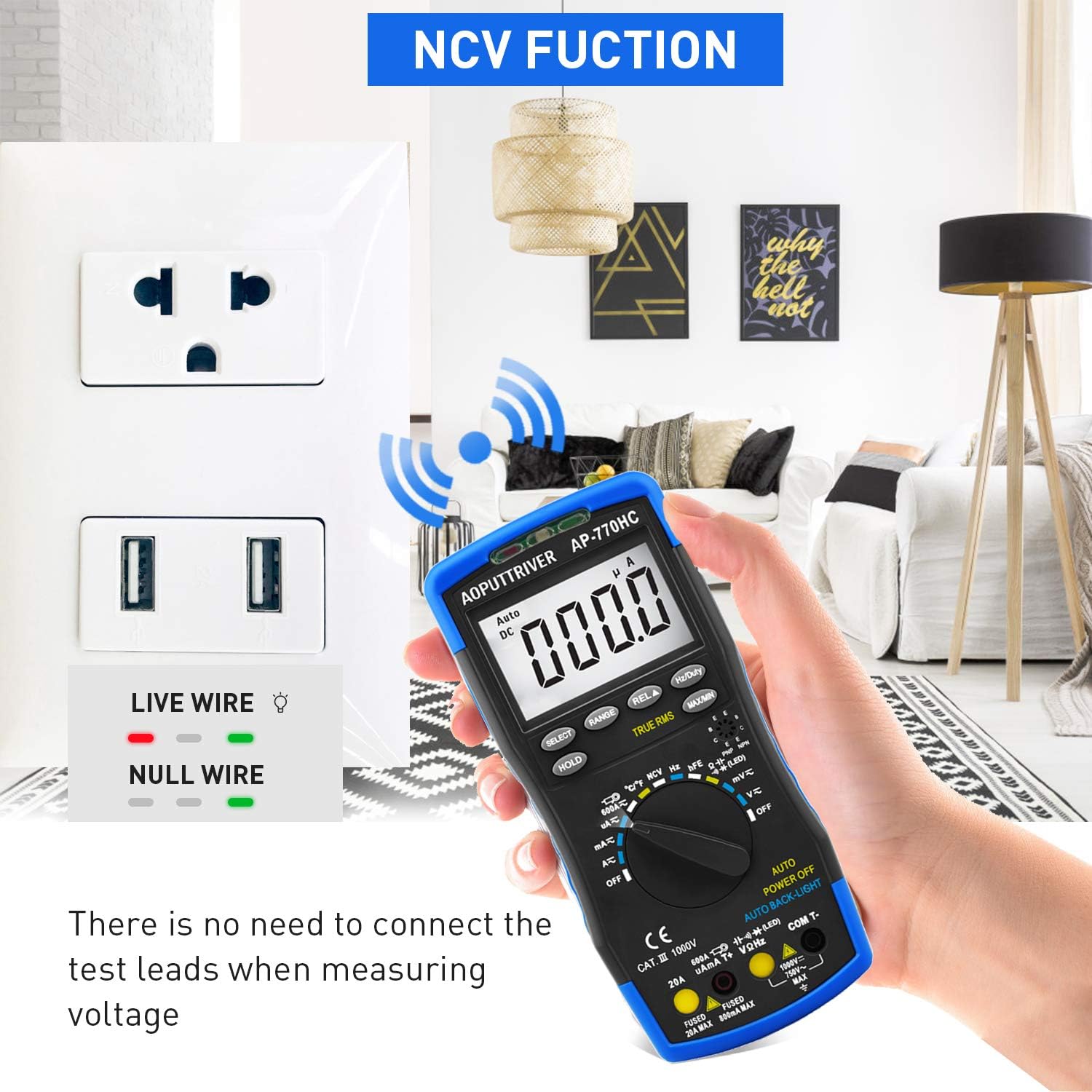
Image: The multimeter's NCV function in use, detecting voltage near an electrical outlet without physical contact.
6.3 Special Functions
- Data Hold (HOLD): Press the HOLD button to freeze the current reading on the display. Press again to release.
- MAX/MIN: Press the MAX/MIN button to record the maximum and minimum values during a measurement session. Press again to cycle through MAX, MIN, and current readings.
- True RMS: The AP-770HC features True RMS measurement for accurate readings of non-sinusoidal AC waveforms.
- Auto Power Off: The meter will automatically power off after approximately 15 minutes of inactivity to conserve battery life.
- Backlight: The display backlight automatically activates in low-light conditions via the CDS sensor.
7. Maintenance
7.1 Cleaning
To clean the multimeter, wipe the case with a damp cloth and a mild detergent. Do not use abrasives or solvents. Ensure the meter is completely dry before use.
7.2 Battery Replacement
When the low battery indicator appears on the display, replace the 9V battery as described in Section 5.1. Always use a fresh 9V (6F22) battery.
8. Troubleshooting
If you encounter issues with your AP-770HC multimeter, refer to the following common problems and solutions:
| Problem | Possible Cause | Solution |
|---|---|---|
| No display or dim display | Dead or low battery; Incorrect battery installation | Replace the 9V battery; Ensure correct polarity during installation. |
| "OL" (Overload) displayed | Measurement exceeds the selected range; Open circuit | Switch to a higher range (if not in auto-ranging); Check for breaks in the circuit or faulty component. |
| Inaccurate readings | Low battery; Incorrect function/range selection; Damaged test leads; External interference | Replace battery; Verify function and range; Inspect and replace test leads if damaged; Move away from strong electromagnetic fields. |
| No continuity beep | Open circuit; Resistance too high | Check the circuit for breaks; Ensure resistance is below the continuity threshold. |
9. Specifications
Technical specifications for the AOPUTTRIVER AP-770HC Digital Multimeter:
| Parameter | Specification |
|---|---|
| Display | 6000 Counts |
| Range Selection | Auto Ranging |
| DC Voltage | 60mV/600mV/6V/60V/600V ±(0.5%+2dgt) / 1000V ±(0.8%+2dgt) |
| AC Voltage | 60mV/600mV/6V/60V/600V ±(1.0%+10dgt) / 750V ±(1.5%+3dgt) |
| DC Current | 600μA/6000μA/60mA/600mA ±(1.5%+2dgt); 6A/20A ±(2.5%+5dgt) |
| AC Current | 600μA/6000μA/60mA/600mA ±(1.5%+3dgt); 6A/20A ±(2.5%+5dgt) |
| Resistance | 600Ω~60MΩ |
| Capacitance | 9.999nF~99.99mF |
| Frequency | 5.12Hz~5.12MHz (0.1%+5dgt) |
| Duty Cycle | 0.1%~99.9% |
| Temperature | -20℃~1000℃ (-4℉~1832℉) |
| True RMS | Yes |
| NCV Function | Yes |
| Data Hold | Yes |
| MAX/MIN Value | Yes |
| Auto Power Off | Yes |
| Backlight Display | Yes |
| Power Source | 9V (6F22) Battery |
| Material | ABS |
| Item Weight | 1.3 pounds |
| Dimensions | 9 x 5.2 x 2.4 inches (Package) |
10. Warranty and Support
AOPUTTRIVER provides a 2-Year Warranty for the AP-770HC Digital Multimeter, along with lifetime technical support.
If you encounter any issues or have questions regarding your product, please do not hesitate to contact AOPUTTRIVER customer support. We are committed to resolving any problems within 24 hours.
For support, please refer to the contact information provided with your purchase or visit the official AOPUTTRIVER website.


