Introduction
This manual provides detailed instructions for the assembly, installation, and maintenance of your Gdrasuya10 PC Frame Test Bench. Designed for enthusiasts and professionals, this open-air chassis supports ITX, ATX, and MATX motherboards, offering excellent heat dissipation and ease of component access. Please read these instructions carefully before beginning assembly to ensure proper setup and optimal performance.
Product Features
- Motherboard Compatibility: Supports ITX, ATX, and MATX motherboards, providing ample space for high-performance components.
- Open-Air Design: Facilitates superior heat dissipation and easy access for component installation, testing, and maintenance.
- Durable Construction: Crafted from high-quality 20x20 aluminum alloy for stability and durability.
- DIY Friendly: Simple structure allows for easy assembly, enhancing the DIY experience.
- Stackable Design: Nude building blocks frame is lightweight and designed for convenient disassembly and stacking.
- Power Supply Support: Compatible with standard ATX power supplies.
Package Contents
Before starting assembly, please verify that all components listed below are present in your package. Refer to the image for visual confirmation of parts.

Image: All components included in the Gdrasuya10 PC Frame Test Bench package. This includes aluminum profiles, various screws, nuts, brackets, a power button, and a transparent acrylic panel.
- Aluminum Profiles (various lengths)
- Motherboard Set Screws
- P3 Set Screws
- HDD/PSU Set Screws
- SSD Set Screws
- B4 Set Screws
- B1 Set Screws
- B2/B3 Set Screws
- Aluminum Profile Slot Nuts
- Graphics Card Set Screws
- Fan Set Screws
- Radiator Set Screws
- Self-adhesive Non-slip Pads
- Power Button with Cable
- Acrylic Panels (Motherboard tray, GPU support, etc.)
- Allen Wrench
Assembly Instructions
Follow these steps carefully to assemble your PC Frame Test Bench. It is recommended to wear gloves during assembly to prevent fingerprints and scratches.
Step 1: Prepare the Base Frame
Identify the aluminum profiles and corner fittings. Use the provided Allen wrench to tighten the screws on the corner fittings.
Video: Demonstrates the initial unboxing and assembly of the base frame components, including securing corner fittings to aluminum profiles.
Assemble the base frame using the aluminum profiles and corner fittings. Ensure all connections are secure.

Image: The base frame of the test bench, showing the assembled aluminum profiles forming the foundation.
Step 2: Install Motherboard Tray and Side Panels
Attach the motherboard tray to the base frame. Ensure the grooves on the bottom plate face downwards. Then, attach the side panel, making sure its grooves also face downwards.
Video: A short preview demonstrating the correct orientation and attachment of the motherboard tray and side panel to the base frame.
Secure the motherboard tray and side panel using the appropriate screws (e.g., Motherboard Set Screws, P3 Set Screws) and nuts. Refer to the included diagram for specific screw placement.
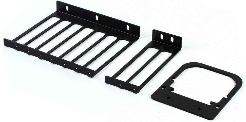
Image: Close-up of the motherboard tray and side panel being secured with screws, highlighting the mounting points.
Step 3: Mount the Motherboard and GPU
Carefully place your motherboard onto the standoffs on the motherboard tray. Secure it with the Motherboard Set Screws. Ensure the motherboard is aligned correctly with the I/O shield opening.
Video: Shows the process of installing an ITX motherboard onto the test bench frame and securing it with screws.
Install the graphics card onto the motherboard's PCIe slot. Use the Graphics Card Set Screws to secure the GPU bracket to the frame.
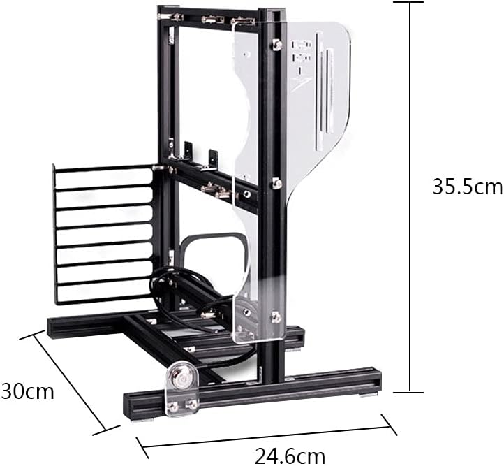
Image: A graphics card is shown installed in the test bench, demonstrating how it fits into the frame.
Step 4: Power Supply and Storage Installation
Mount the power supply unit (PSU) using the HDD/PSU Set Screws and the designated bracket. Ensure the PSU is securely attached to the frame.

Image: A power supply unit is mounted on the test bench, showing its position relative to the motherboard and GPU.
Install any SSDs or HDDs using the SSD Set Screws or HDD/PSU Set Screws and appropriate brackets. Connect all necessary power and data cables.
Step 5: Final Touches and Power-On
Attach the power button to the designated slot on the frame and connect its cables to the motherboard's front panel headers.

Image: The power button is shown installed on the test bench frame, ready for connection to the motherboard.
Connect all remaining power cables (24-pin ATX, CPU, PCIe for GPU) and data cables (SATA, USB, etc.) to their respective components.
Once all components are securely installed and connected, plug in the power cable to the PSU and press the power button to initiate the system.
Operating Instructions
The Gdrasuya10 PC Frame Test Bench is designed for ease of use and accessibility. To operate your system:
- Power On/Off: Use the integrated power button to turn the system on or off.
- Component Access: The open-air design allows for quick and easy swapping of components like GPUs, RAM, and storage drives without needing to open a traditional case.
- Testing: Ideal for testing new hardware, overclocking, or troubleshooting, thanks to its accessible layout.
Maintenance
Regular maintenance ensures the longevity and optimal performance of your test bench:
- Dust Removal: Due to its open design, dust accumulation can occur. Regularly use compressed air to clean components and the frame.
- Acrylic Panel Care: Clean acrylic panels with a soft, damp cloth and mild soap. Avoid abrasive cleaners that can scratch the surface.
- Screw Tightness: Periodically check all screws and connections to ensure they remain tight and secure.
Troubleshooting
If you encounter issues, consider the following common troubleshooting steps:
- System Not Powering On:
- Check all power connections, especially the 24-pin ATX and CPU power cables to the motherboard, and the power cable to the PSU.
- Ensure the power button is correctly connected to the motherboard's front panel headers.
- Verify the PSU switch is in the "on" position.
- No Display Output:
- Ensure the graphics card is fully seated in its PCIe slot and any necessary PCIe power cables are connected.
- Verify the monitor cable is securely connected to the graphics card (not the motherboard's integrated graphics ports, unless using integrated graphics).
- Component Instability:
- Check that all components (motherboard, GPU, RAM, storage) are securely mounted and properly connected.
- Ensure all screws are tightened appropriately.
Specifications
| Feature | Detail |
|---|---|
| Brand | Gdrasuya10 |
| Model Name | Gdrasuya10 |
| Motherboard Compatibility | Micro ATX, ITX, ATX |
| Case Type | Midi Tower (Open Frame) |
| Material | Aluminum |
| Color | Black |
| Item Weight | 1.1 pounds (approx. 500 Grams) |
| Product Dimensions (LxWxH) | 13.98 x 9.69 x 13.98 inches |
| Cooling Method | Air / Water (Open Frame Design) |
| Power Supply Mounting Type | Bottom Mount |
Warranty and Support
Gdrasuya10 is committed to providing quality products and customer satisfaction. For any issues or inquiries:
- 24-Hour Service: We provide 24-hour online service and email support.
- Quality Control: Every product undergoes strict quality control before sale.
- Contact Us: If the product is defective or cannot be installed, please contact us first. We will endeavor to resolve your problem promptly.
