1. Introduction
This instruction manual provides comprehensive guidance for the safe and effective use of your Nilight 6 Gang Switch Panel. Please read this manual thoroughly before installation and operation to ensure proper functionality and to prevent damage. This universal circuit control relay system is designed to manage up to six auxiliary LED lights and electrical accessories in various vehicles including cars, trucks, boats, ATVs, UTVs, and SUVs.

Image: The Nilight 6 Gang Switch Panel, including the switch pod, circuit control box, and associated wiring.
2. Product Overview and Components
The Nilight 6 Gang Switch Panel system integrates a switch pod, circuit control relay box, fuses, and wiring harness into a single unit for streamlined control of your vehicle's accessories. Key components include:
- 6 Gang Switch Panel: Controls up to six devices with dimmable LED backlighting.
- Circuit Control Box: Houses relays and fuses for protection and power distribution.
- Wiring Harness: Pre-wired for plug-and-play installation.
- 50pcs Reusable Stickers: For customizing switch labels.
- Mounting Options: Includes double-sided tape and an adjustable mount bracket for the switch panel.

Image: A visual representation of all items included in the Nilight 6 Gang Switch Panel package, such as the switch panel, circuit control box, fuses, labels, and mounting hardware.
3. Setup and Installation
Follow these steps for proper installation of your Nilight 6 Gang Switch Panel. Ensure the vehicle's power is disconnected before beginning any wiring.
3.1. Wiring Connections
- Connect the main power cable from the circuit control box to the positive terminal of your vehicle's 12V DC battery.
- Connect the ground cable from the circuit control box to the negative terminal of your vehicle's battery or a suitable chassis ground point.
- Connect the switch panel to the circuit control box using the provided plug-and-play wiring harness.
- Connect your auxiliary lights or electrical accessories to the designated output terminals on the circuit control box. Each output is protected by a fuse and relay.

Image: A detailed diagram illustrating the connections for the switch panel, circuit control box, battery, and auxiliary devices, highlighting the fuse and relay system.

Image: An illustration demonstrating how different types of auxiliary lights can be connected and controlled by the 6 Gang Switch Panel.
3.2. Switch Panel Mounting
The switch panel offers two primary mounting methods:
- Double-Sided Tape: For a flush, non-invasive mount on flat surfaces like the dashboard or center console. Ensure the surface is clean and dry before applying.
- Adjustable Mount Bracket: For a more secure and adjustable installation, allowing for optimal viewing angles. Secure the bracket to a stable surface using screws, then attach the switch panel to the bracket.
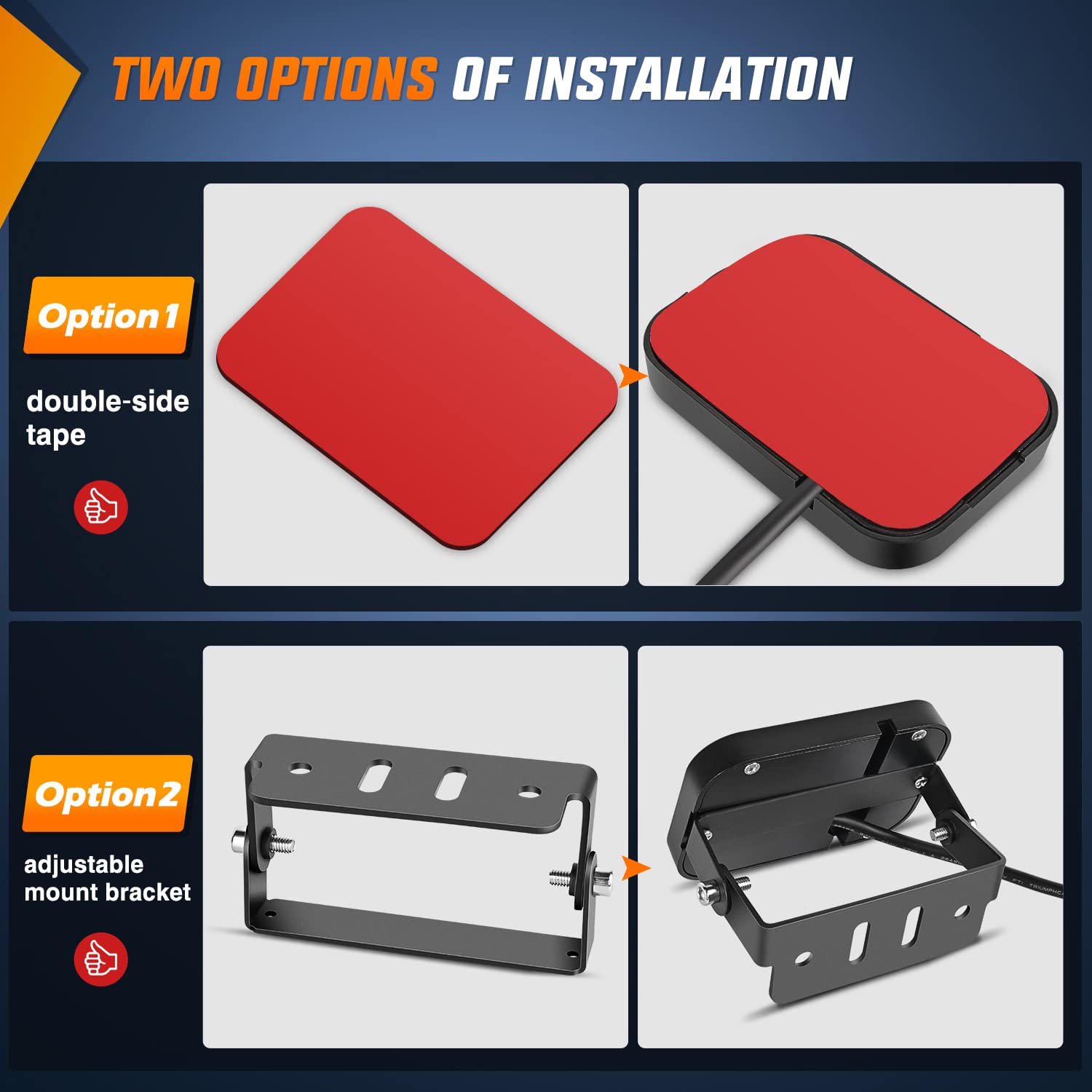
Image: A visual comparison of the two available mounting options for the switch panel, showing both the double-sided tape method and the adjustable bracket installation.
3.3. Circuit Control Box Mounting
Mount the circuit control box in a secure, dry location away from excessive heat or moisture. Common locations include under the hood or within the vehicle's cabin, ensuring easy access for maintenance if needed. Use appropriate fasteners to secure the box firmly.
4. Operation
4.1. Basic Functionality
Each button on the 6 Gang Switch Panel controls a connected accessory. Press a button to turn the corresponding accessory ON, and press it again to turn it OFF. The LED indicator above each button will illuminate when the accessory is active.
4.2. Dimmable Backlight
The switch panel features an automatic dimmable backlight function. The brightness of the button backlighting adjusts automatically based on the ambient light conditions, providing optimal visibility during both day and night driving without causing glare.

Image: A series of images demonstrating the automatic dimming feature of the switch panel's backlight, showing its appearance in various lighting environments from bright daylight to nighttime.
4.3. Customizing Switch Labels
The kit includes 50 reusable stickers with various common accessory icons. To customize your switch panel:
- Select the appropriate sticker for each function you wish to label.
- Carefully peel the sticker and apply it directly onto the transparent cover of the desired switch button.
- The stickers are reusable, allowing you to change labels as needed.

Image: A sheet displaying 50 different reusable labels with various icons for customizing the functions of the switch panel buttons.
5. Maintenance
To ensure the longevity and optimal performance of your Nilight 6 Gang Switch Panel:
- Regularly inspect all wiring connections for tightness and signs of wear or corrosion.
- Keep the switch panel and control box clean and free from dust and debris. Use a soft, dry cloth for cleaning.
- Check fuses periodically and replace any blown fuses with ones of the correct amperage (as indicated on the circuit control box).
6. Troubleshooting
If you encounter issues with your switch panel, consider the following common solutions:
- No Power to Panel/Accessories:
- Check the main power connection to the battery.
- Verify that the circuit breaker (if installed) has not tripped.
- Inspect all fuses in the control box for continuity and replace any blown fuses.
- Individual Accessory Not Working:
- Ensure the specific button on the switch panel is pressed ON.
- Check the fuse for that particular circuit in the control box.
- Inspect the wiring connection from the control box to the accessory.
- Backlight Not Dimmable:
- Ensure the brightness sensor on the switch panel is not obstructed.
The system includes built-in safety features such as over-voltage protection, over-current protection, overheat protection, and reverse polarity protection. If these protections are triggered, the system may temporarily shut down to prevent damage. Address the underlying issue before attempting to restart the system.
7. Specifications
| Feature | Specification |
|---|---|
| Input Voltage | 12V DC |
| Max. Output Power | 720W |
| Max. Input Current | 60A |
| Switch Panel Size | 3.74" x 2.65" |
| Circuit Control Box Size | 6.26" x 3.52" x 3.27" |
| Operating Temperature | -40°C to +105°C |
| Protection Features | Over-Voltage, Over-Current, Overheat, Reverse Polarity |
| IP Rating | IP54 |
| Material | ABS (Switch Panel, Control Box), Aluminum (Contact) |
8. Warranty and Support
The Nilight 6 Gang Switch Panel comes with a 2-year warranty. For technical support, warranty claims, or any questions regarding your product, please contact Nilight customer service through their official website or the retailer where the product was purchased. Please have your model number (50059R) and purchase information ready.