
ATNSINC 19089
ATNSINC FT232RL USB to TTL Adapter User Manual
Model: 19089
1. Introduction
The ATNSINC FT232RL USB to TTL Adapter (Model 19089) is a versatile serial converter designed for development projects and communication with TTL-level devices. Featuring a genuine FTDI FT232RL IC, this adapter provides stable and reliable USB to UART conversion, making it compatible with a wide range of operating systems including Windows, Linux, and Mac OS. It offers a convenient switch for selecting between 3.3V and 5V logic levels, and includes indicator LEDs for power and data transmission.
2. Product Features
- Genuine FTDI FT232RL IC: Ensures stable and reliable USB to UART communication.
- Voltage Select Switch: Easily switch between 3.3V and 5V logic levels.
- Plug and Play: Simple connection to PC/laptop via USB, drawing power directly.
- UART Access: Provides access to Transmit (Tx), Receive (Rx), RTS#, CTS#, VCC, and GND connections.
- Transceiver LEDs: Includes LEDs for Power (POW), Receive (RXD), and Transmit (TXD) to indicate data flow.
- Broad OS Compatibility: Supports Windows (7/8/10/XP), Linux (2.4 and above), Mac OS (8/9, X and above), and Android (J2xx). Note: Not compatible with Chrome OS.
- Wide Application Range: Suitable for USB to RS232/RS422/RS485 conversions, EEPROM support, router unbricking, GPS module interfacing, MCU program download, and firmware flashing.
3. Product Overview
Familiarize yourself with the components and dimensions of the FT232RL USB to TTL Adapter.

Figure 3.1: FT232RL USB to TTL Adapter with overall dimensions (65mm x 26.5mm x 46mm).

Figure 3.2: Key components and pinout of the adapter, including the FTDI IC, 3.3V/5V switch, and indicator LEDs.
3.1 Component Identification
- FTDI IC: The central processing unit for USB to serial conversion.
- 3.3V/5V Switch: A physical switch to select the output voltage for VCC and logic levels for TXD/RXD.
- POW LED: Illuminates when the adapter is powered.
- RXD LED: Flashes when data is being received by the adapter.
- TXD LED: Flashes when data is being transmitted by the adapter.
- Gold Plated Pins: Provides connections for CTS, RTS, RXD, TXD, GND, and VCC.
- USB Connector: Standard USB-A connector for connecting to a host computer.
4. Setup Instructions
4.1 Driver Installation
The FT232RL adapter requires specific drivers for proper operation on your computer. In many modern operating systems (Windows 10, recent Linux distributions, Mac OS), drivers may install automatically upon first connection. If not, manual installation is required.
- Download Drivers: Visit the official FTDI website for the latest Virtual COM Port (VCP) drivers: https://www.ftdichip.com/Drivers/VCP.htm
- Installation Guides: For detailed installation instructions specific to your operating system, refer to the FTDI installation guides: https://www.ftdichip.com/Support/Documents/InstallGuides.htm

Figure 4.1: Driver download and installation guide references.
4.2 Voltage Selection (3.3V / 5V)
Before connecting the adapter to your target device, ensure the correct voltage level is selected using the onboard switch. This switch controls both the VCC output pin and the logic levels for the TXD/RXD signals.
- 5V Position: Select this for devices that operate at 5V logic levels and require 5V power.
- 3.3V Position: Select this for devices that operate at 3.3V logic levels and require 3.3V power.
Caution: Connecting the adapter with an incorrect voltage setting can damage your target device. Always verify the required voltage of your device before connecting.
4.3 Connecting to a Target Device
Connect the adapter to your target device using the appropriate pins. A common connection scheme for basic serial communication (UART) is as follows:
- Adapter TXD to Target RXD
- Adapter RXD to Target TXD
- Adapter GND to Target GND
- Adapter VCC to Target VCC (Optional, if powering the target device from the adapter. Ensure correct voltage selection.)
- CTS/RTS: These pins are used for hardware flow control. Connect them if your application requires flow control.
5. Operating Instructions
5.1 Signal Descriptions
Understand the function of each pin on the adapter's header.
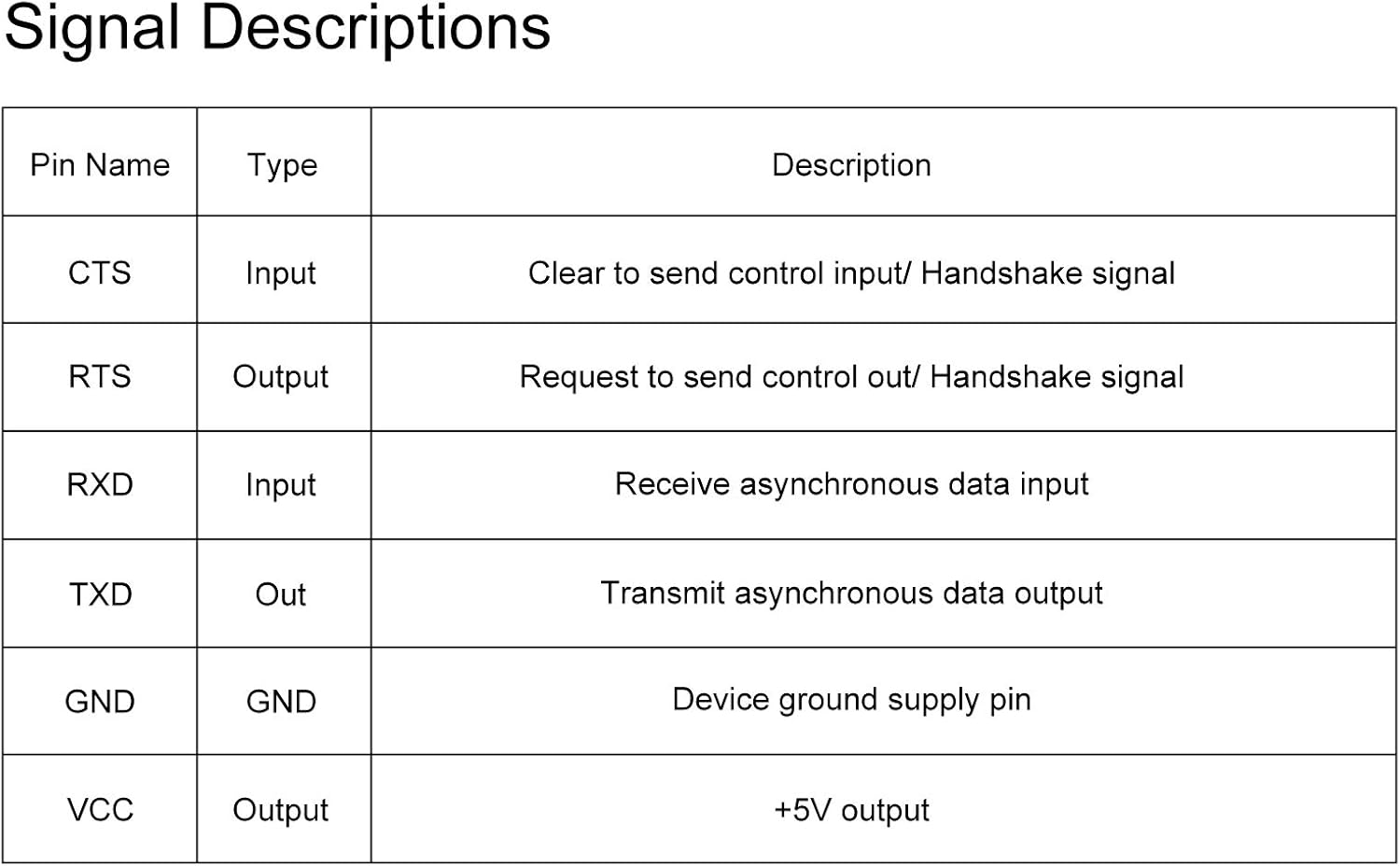
Figure 5.1: Detailed description of each pin's function.
| Pin Name | Type | Description |
|---|---|---|
| CTS | Input | Clear to Send control input / Handshake signal |
| RTS | Output | Request to Send control output / Handshake signal |
| RXD | Input | Receive asynchronous data input |
| TXD | Output | Transmit asynchronous data output |
| GND | GND | Device ground supply pin |
| VCC | Output | +5V or +3.3V output (selectable via switch) |
5.2 LED Indicators
- POW (Power) LED: This LED illuminates when the adapter is connected to a USB port and receiving power.
- RXD (Receive) LED: This LED flashes when the adapter is receiving data from the connected target device.
- TXD (Transmit) LED: This LED flashes when the adapter is transmitting data to the connected target device.
5.3 Supported Applications
The FT232RL USB to TTL Adapter is suitable for a variety of applications, including but not limited to:

Figure 5.2: Examples of common applications for the adapter.
- USB to RS232/RS422/RS485 converters
- Support for EEPROM and Vendor ID re-write
- Unbricking routers and Mprog3.5 applications
- Interfacing with GPS modules
- Microcontroller (MCU) program download
- Flashing firmware on hard drives
- Updating transmitters
- Working with microcontrollers or other programmable devices
- Upgrading set-top box systems
6. Troubleshooting
- Adapter Not Recognized:
- Ensure the adapter is firmly plugged into a USB port.
- Verify that the drivers are correctly installed. Refer to Section 4.1.
- Try a different USB port or a different computer to rule out port issues.
- No Data Transmission/Reception:
- Check your wiring connections (TXD to RXD, RXD to TXD, GND to GND).
- Confirm the correct voltage (3.3V/5V) is selected on the adapter for your target device.
- Ensure the baud rate, data bits, parity, and stop bits settings in your serial terminal software match those of your target device.
- Verify that the target device is powered and functioning correctly.
- Observe the RXD/TXD LEDs for activity. If they are not flashing, no data is being sent or received.
- Device Damage After Connection:
- This often indicates an incorrect voltage selection. Always double-check the voltage requirements of your target device and set the adapter's switch accordingly before connecting.
7. Specifications
| Feature | Detail |
|---|---|
| Model Number | 19089 |
| Chipset | Genuine FTDI FT232RL |
| Interface | USB to TTL UART |
| Logic Voltage | 3.3V / 5V (Switchable) |
| Connector Type | USB-A |
| Operating System Compatibility | Windows 7/8/10/XP, Linux 2.4+, Mac OS 8/9/X+, Android (J2xx) |
| Package Dimensions | 3.11 x 2.17 x 0.28 inches |
| Item Weight | 0.458 ounces |
| Manufacturer | Atnsinc |
8. Warranty and Support
This ATNSINC product is covered by a standard manufacturer's warranty. For specific warranty details, technical support, or further assistance, please contact ATNSINC customer service through your purchase platform or the official ATNSINC website. Please have your product model number (19089) and purchase information ready when contacting support.
Ask a question about this manual
Ask about setup, troubleshooting, compatibility, parts, safety, or missing instructions. Manuals+ will review the question and use this page’s manual context to help answer it.